In this project, SOLIDWORKS Flow Simulation and Markforged Simulation were used to optimize a reinforcement bracket for a race car before it was manufactured. Aerodynamic simulation helped determine the loads acting on the part, while Eiger was used to optimize its print orientation, infill, and continuous carbon fiber reinforcement. The final 3D-printed part achieved a worst case safety factor of 2.18 while keeping material usage and manufacturing costs under control.
From the Racetrack to Additive Manufacturing
A difference in handling between the left and right sides of a race car may seem minor. At high speeds, however, it can reveal an important mechanical or aerodynamic issue.
That is exactly what happened with one of the vehicles sponsored by Solidxperts. The driver noticed a difference in how the car behaved from one side to the other. After several inspections, the team discovered that the splitter, the component located at the front and underneath the vehicle, had partially detached on one side.
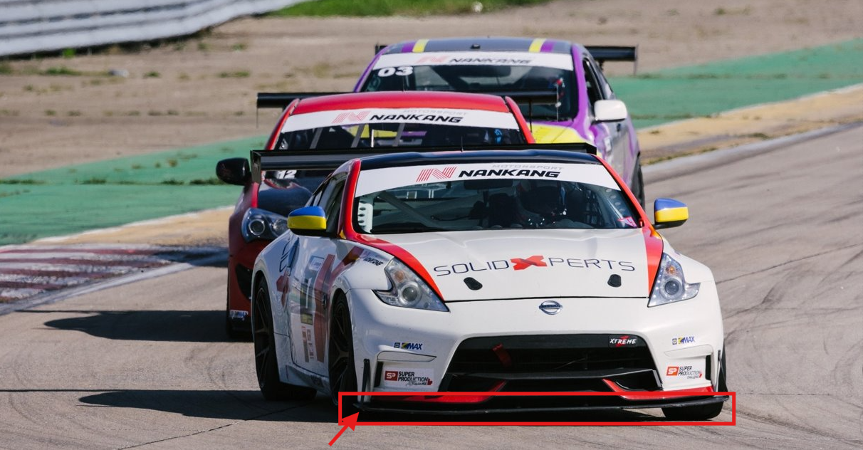
A reinforcement bracket was needed to securely hold the splitter in place without negatively affecting the vehicle’s aerodynamics. Since only a small number of vehicles required the part, additive manufacturing offered a fast and cost-effective solution.
The project followed three main steps:
-
Optimize the bracket geometry using SOLIDWORKS Flow Simulation.
-
Determine the loads that the part would need to withstand.
-
Optimize its print orientation and manufacturing parameters using Markforged Simulation in Eiger.
Why Simulate a Part Before 3D Printing It?
Simulation makes it possible to evaluate multiple concepts virtually before spending time and material on physical prototypes. It can help answer practical questions such as:
-
Does the part’s shape increase aerodynamic drag?
-
Will the component withstand the expected loads?
-
Which print orientation provides the best mechanical performance?
-
Where should continuous carbon fiber be added?
-
Can the required safety factor be achieved without unnecessarily increasing cost?
In this project, simulation created a link between design and manufacturing. The results from the fluid analysis were used to define the structural loads, and the printing parameters were then adjusted based on the stresses acting on the part.
Step 1: Optimizing Aerodynamics with SOLIDWORKS Flow Simulation
Defining Realistic Operating Conditions
SOLIDWORKS Flow Simulation is directly integrated into SOLIDWORKS. Its setup tools guide users through the definition of fluids, units, boundary conditions, and simulation goals.
To reproduce a demanding operating condition, the team simulated a total relative air speed of 300 km/h, representing a vehicle traveling at 200 km/h with a 100 km/h headwind.
The primary objective was to measure the drag force acting on the reinforcement bracket. This value would later be used as an input load for the structural validation of the part.
Creating an Appropriate Mesh
The mesh divides the simulation domain into small cells where the software solves the fluid flow. Local mesh refinement can be applied around surfaces and details that have a greater influence on the results.
A mesh preview makes it possible to review the setup before running the calculation. This is an important step, since a simulation is only as reliable as the assumptions, boundary conditions, and mesh used to represent the real-world situation.
Evaluating the Airflow and Measuring Drag
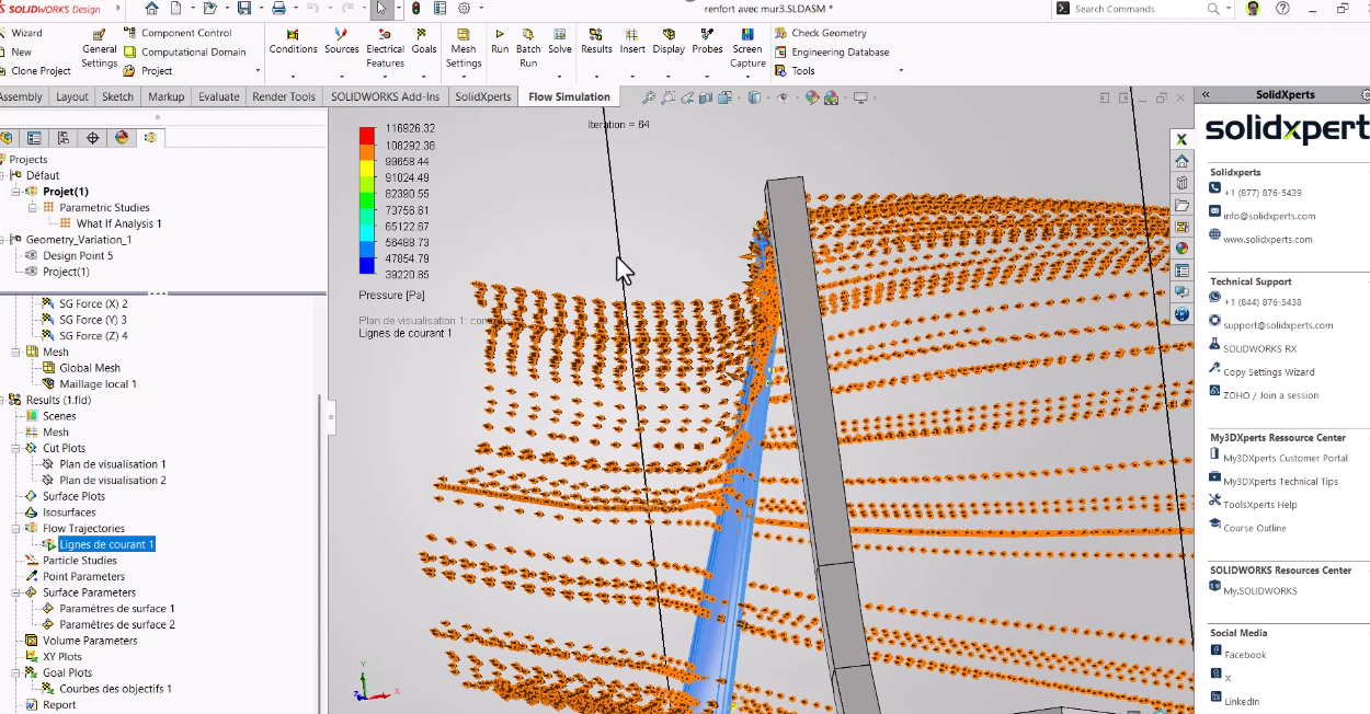
Once the calculation was complete, flow trajectories made it possible to visually confirm how the air moved around the part. The first configuration produced a drag force of approximately 14 to 15 N.
To maintain a conservative margin, the team also analyzed the part without considering the beneficial aerodynamic effect of the vehicle body. This more severe scenario produced approximately 20 N of drag, and this value was retained for the next stage of the project.
Automating Geometry Optimization
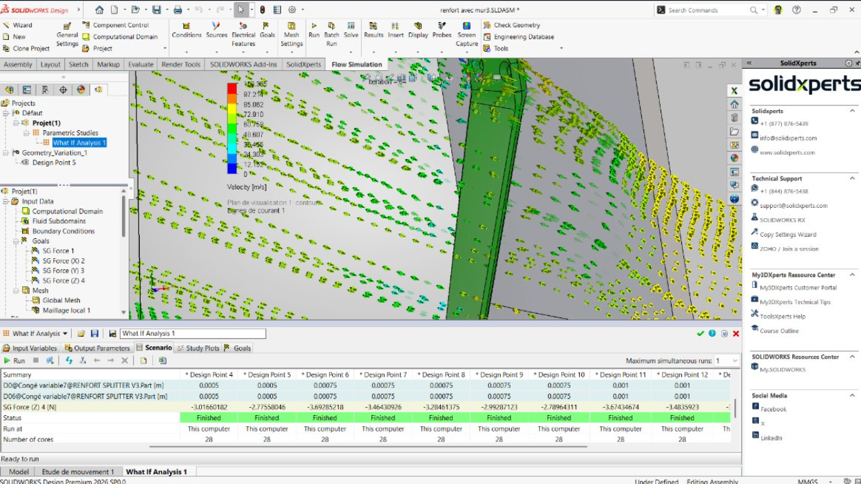
A design study can automatically vary several parameters, including:
-
The radius of the leading edge
-
The thickness of the part
-
Its angle
-
Other dimensions that influence the airflow
Instead of manually modifying and recalculating each version, the software can compare multiple scenarios to identify the geometry that minimizes drag. This approach reduces the number of physical prototypes required and speeds up concept validation.
Step 2: Turning Simulation Results into Strength Requirements
Once the bracket geometry had been defined, the next step was to establish the design loads. Three objectives were selected:
-
Withstand an aerodynamic load of 40 N, representing the conservative 20 N drag force multiplied by a factor of two.
-
Support a vertical load of 25 N per screw, for a total of 50 N, representing the weight and forces acting on the splitter.
-
Achieve an overall safety factor greater than 2.
These conditions were then reproduced in Eiger.
The upper connection to the vehicle body was modeled as a fixed constraint, while the lower mounting points were represented by supports that allowed certain movements while restricting the required transverse motion.
Step 3: Choosing the Best Markforged Print Orientation
Why Does Print Orientation Affect the Strength of a 3D-Printed Part?
A 3D-printed part does not have the same mechanical properties in every direction. The material is generally weaker along the Z-axis, which corresponds to the direction in which layers are stacked, due to the nature of interlayer bonding.
The goal is therefore to orient the part so that its weakest direction is exposed to the lowest stresses.
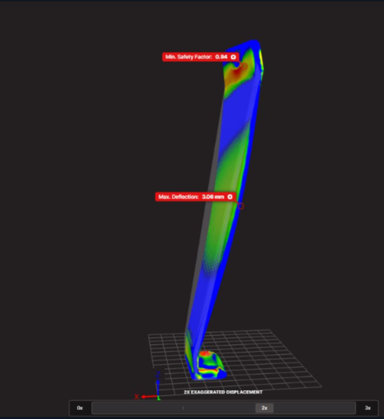
Two orientations were compared in Eiger:
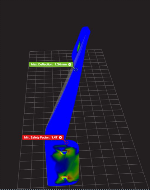
|
Print Orientation |
Safety Factor |
Estimated Cost |
Result |
|---|---|---|---|
|
Vertical |
0.94 |
$10.89 |
Insufficient strength |
|
Horizontal |
1.47 |
$11.06 |
56% increase in safety factor |
The horizontal orientation increased the safety factor by 56%, while the estimated cost increased by only about 1.5%. It was therefore selected as the starting point for the final optimization.
The costs presented in this case study are specific to the project and are primarily intended to compare different configurations. Actual costs may vary depending on the material, machine, print settings, and production conditions.
Step 4: Optimizing Infill and Continuous Carbon Fiber Reinforcement
After selecting the print orientation, the team compared several manufacturing parameters, including:
-
Infill density and pattern
-
Number of walls
-
Number of floor and roof layers
-
Placement of continuous fiber
-
Total material usage
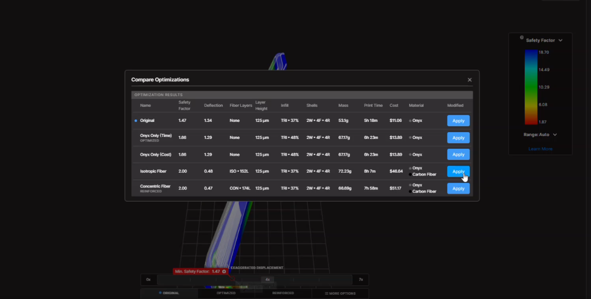
Eiger’s optimization capabilities proposed a continuous carbon fiber-reinforced configuration capable of exceeding the target safety factor.
The automatically generated configuration was then refined further. Fiber layers that were initially adjacent to one another were separated by a layer of Onyx, as the bonding between Onyx and fiber can be preferable to stacking fiber directly against fiber.
The fiber groups were also distributed toward the upper and lower regions of the part to create a structure similar to a sandwich panel.
This arrangement improves stiffness while placing reinforcement where it provides the greatest benefit.
The Result: A Part Validated Before Manufacturing
The final configuration achieved a safety factor of 2.18, exceeding the original target of 2.
The estimated manufacturing cost remained around $30, while still being lower than some of the configurations proposed during the optimization process.
The workflow made it possible to develop a reinforcement bracket that met the project’s three main objectives:
-
Minimize aerodynamic impact
-
Withstand the loads experienced on the racetrack
-
Reduce both manufacturing costs and the number of physical iterations
What Are the Benefits of Combining SOLIDWORKS and Markforged Simulation?
Using SOLIDWORKS Flow Simulation together with Markforged Simulation creates a digital workflow that connects design, validation, and manufacturing.
This approach makes it possible to:
-
Measure realistic loads instead of relying on arbitrary estimates
-
Quickly compare multiple geometries
-
Reduce the number of physical prototypes
-
Select a print orientation based on mechanical performance
-
Strategically place continuous fiber reinforcement
-
Balance cost, print time, and part performance
-
Accelerate the production of low-volume parts
For automotive, industrial, and manufacturing applications, this workflow helps engineers make better decisions before the first physical part is even printed.
From Analysis to a Production-Ready Part
A high-performance 3D-printed part depends on more than its geometry. Its performance is also influenced by the actual loads it experiences, its print orientation, the selected material, and the placement of reinforcement.
The experts at Solidxperts can help you integrate SOLIDWORKS Flow Simulation and Markforged solutions into your product development process. By validating concepts earlier, you can reduce iterations and manufacture parts that are better suited to their real-world operating environment.
From Analysis to a Production-Ready Part
A high-performance 3D-printed part depends on more than its geometry. Its performance is also influenced by the actual loads it experiences, its print orientation, the selected material, and the placement of reinforcement.
The experts at Solidxperts can help you integrate SOLIDWORKS Flow Simulation and Markforged solutions into your product development process. By validating concepts earlier, you can reduce iterations and manufacture parts that are better suited to their real-world operating environment.
Contact our experts to discuss your next simulation or additive manufacturing project.