GRYB uses SOLIDWORKS Simulation to identify critical stress areas, validate structural performance and optimize heavy equipment attachments before manufacturing. By replacing part of its physical prototyping and destructive testing process with finite element analysis, the company can develop lighter, stronger products, take on more custom projects and move toward production with greater confidence.
That matters when every design must withstand demanding real-world loads. Choosing the wrong material thickness can create two costly problems: an underdesigned product that may fail, or an overdesigned product that uses more steel, weighs more and costs more than necessary.
In this customer story, GRYB explains how simulation became a core part of its engineering process and helped turn previously impractical projects into viable products.
At a glance: What did SOLIDWORKS Simulation change for GRYB?
SOLIDWORKS Simulation gave GRYB’s engineering team a practical way to predict structural behaviour before building a physical prototype. The team can now locate high-stress zones, compare design decisions, select appropriate materials and thicknesses, review displacement and factor of safety, and document its analysis. This reduces unnecessary prototypes, supports product optimization and shortens the path from concept to manufacturing.
Who is GRYB?
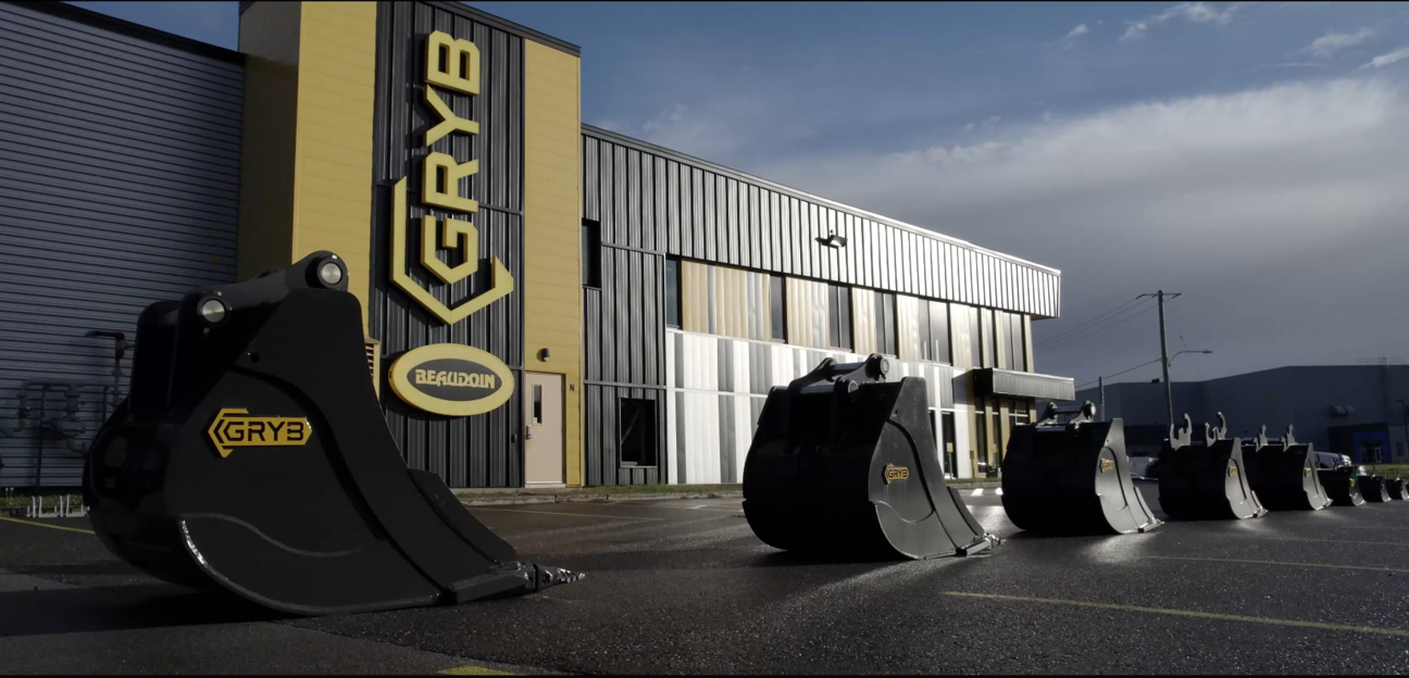
GRYB is a manufacturer of attachments for heavy machinery, including equipment for excavators, loaders and other demanding applications. Founded in 2007, the company has grown from a two-person operation into an international organization whose brand is represented in 20 countries, according to the GRYB website.
Its products serve industries such as construction, excavation, demolition, recycling, material handling and snow removal. Across these applications, GRYB’s goal is consistent: deliver complete solutions that are robust, safe and suited to the customer’s operating requirements.
The company began using SOLIDWORKS Simulation early in its development. According to the webinar, its first use dates back to approximately 2009. Simulation therefore became part of GRYB’s product validation process as the organization and its product catalogue expanded.
What engineering challenges did GRYB face before simulation?
Before adopting simulation, GRYB found it difficult to determine exactly where real stresses would concentrate in a product. That uncertainty affected several design decisions:
-
Where should material be reinforced?
-
Which steel grade should be used in each area?
-
How thick should each component be?
-
Which geometry creates the best balance of strength and weight?
-
Will the design perform as expected under its intended load cases?
Without reliable virtual insight, optimization was slower and more expensive. Physical prototypes and destructive tests consumed material, labour and machine time. If a test revealed a problem, the team had to revise the design, manufacture another prototype and test again.
The alternative was often to design conservatively. Adding material may lower perceived risk, but overdesign can increase product weight, material consumption, manufacturing costs and operating demands. It can also hide the real behaviour of the structure instead of addressing the critical load path.
Why are physical prototypes alone not enough?
Physical testing remains important, especially for final validation, certification and complex real-world behaviour. The limitation is that a prototype usually shows what happened, while simulation can provide more insight into where and why it happened.
Finite element analysis can visualize stress, strain and displacement throughout a structure. Engineers can inspect internal load paths and compare design variants before committing to new material and fabrication.
For one-off or highly customized attachments, building several prototypes may be commercially unrealistic. Virtual testing gives the engineering team a way to evaluate those projects earlier and determine whether a proposed design is viable.
How does SOLIDWORKS Simulation help validate a design?
SOLIDWORKS Simulation is a structural analysis solution that uses finite element analysis, or FEA, to predict how a CAD model will respond to loads, restraints and material properties. Because it is integrated into the SOLIDWORKS design environment, engineers can evaluate a model without rebuilding it in a separate interface.
A typical structural study follows these steps:
-
Define the purpose of the analysis and the expected failure modes.
-
Simplify the CAD model while preserving structural behaviour.
-
Confirm the material properties.
-
Apply fixtures, contacts, connectors and external loads.
-
Create an appropriate finite element mesh.
-
Solve the study and review stress, displacement and other results.
-
Check assumptions, convergence and factor of safety.
-
Modify the design and compare the new results.
-
Document the setup, results and engineering conclusions.
The software performs the calculations, but engineering judgment remains essential. A result is only meaningful when the materials, restraints, contacts, loads and modelling assumptions represent the real application closely enough for the decision being made.
Case study: Validating a directional snow blade
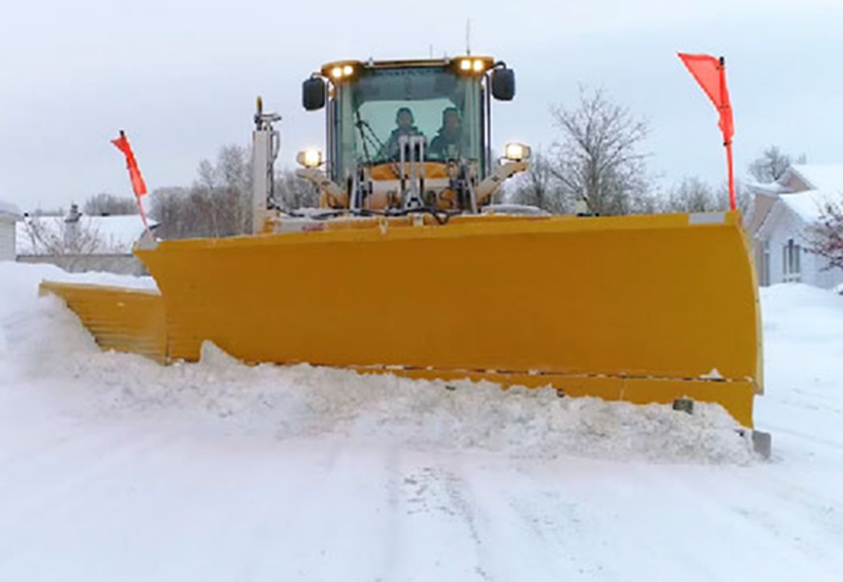
The webinar demonstrates a finite element analysis performed on a directional snow blade developed by GRYB. This product experiences significant forces as it moves snow and changes orientation. Its pivots, welded structures and load-bearing components must transfer those forces safely.
The purpose of the study was to verify that the product would deliver the required structural performance under a defined loading scenario.
Step 1: Simplify the model
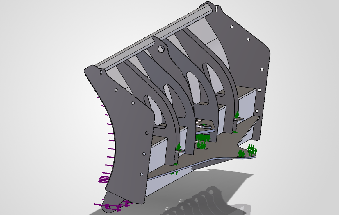
GRYB supplied a simplified 3D model for the analysis. This is a key simulation practice. Running an analysis on every manufacturing detail can add computational cost without improving the answer.
Small cosmetic features, non-structural components and geometry far from the area of interest may be removed when they do not materially affect stiffness or load transfer. The goal is not to create the most detailed model possible. It is to create the simplest model that still represents the relevant physical behaviour.
Model simplification can:
-
reduce meshing and solving time;
-
avoid unnecessary mesh complexity;
-
make contacts and boundary conditions easier to review;
-
help engineers focus on the critical parts of the structure.
Training and experience are important here. Removing the wrong feature can distort stiffness or eliminate a local stress concentration that matters.
Step 2: Transfer and verify materials
Because SOLIDWORKS Simulation is integrated with SOLIDWORKS Design, material assignments from the CAD model can support the study setup. In the webinar example, much of the blade structure uses 44W structural steel, with some exceptions.
Engineers must still verify that the material model and properties match the real product. Yield strength, elastic modulus and other properties directly affect stress interpretation, deformation and factor-of-safety calculations.
Step 3: Apply realistic boundary conditions
The demonstration includes a fixed hinge condition applied to cylindrical faces. Boundary conditions tell the solver how the model is supported and how it can move.
An overly rigid fixture can create artificial stress, while an underconstrained model may move unrealistically or fail to solve. Visual feedback in the software helps users understand the degrees of freedom removed by each restraint, but the setup must still reflect the real mounting condition.
Step 4: Apply the load case
The team then applies a load representing the operating condition to be evaluated. For a directional blade, different positions and loading directions may create different structural responses. A complete validation plan may therefore require more than one load case.
Each case should answer a specific engineering question. For example:
-
What happens under the expected working load?
-
Which orientation creates the highest stress?
-
How does an offset load affect the frame?
-
What happens at the pivots, bolts and welds?
-
Does displacement remain within an acceptable limit?
Step 5: Interpret stress, displacement and safety factor
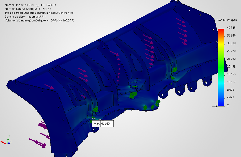
Once solved, the study can display an exaggerated deformation animation that makes the overall structural behaviour easier to understand. Engineers can also review:
-
von Mises stress;
-
strain;
-
displacement;
-
reaction forces;
-
forces in bolts or connectors;
-
weld forces;
-
factor of safety.
These plots help identify risk areas and guide design changes. A single maximum value should not be accepted blindly. Engineers should determine whether the result is physically meaningful, caused by an idealized singularity or sensitive to mesh density and boundary conditions.
What benefits did GRYB gain from SOLIDWORKS Simulation?
1. More targeted structural reinforcement
Simulation helps GRYB identify critical zones instead of adding material throughout a product. Reinforcement can be placed where the load path and stress results show it is needed.
2. Lighter and more robust products
Strength and weight do not always need to move in the same direction. By removing unnecessary material from low-stress areas and improving high-risk zones, engineers can pursue a lighter design without sacrificing required performance.
3. Fewer physical prototypes
Virtual testing allows the team to reject weak concepts and improve promising ones before fabrication. Physical testing can then focus on a more mature design, reducing avoidable prototype iterations.
4. Lower long-term material costs
Material optimization can reduce steel consumption across production volumes. Even modest improvements per unit may become meaningful when applied repeatedly.
5. Faster design decisions
Engineers can compare variants inside the CAD workflow and evaluate the effect of changing geometry, thickness or material. This supports shorter design cycles and a faster path to market.
6. Greater confidence in custom projects
GRYB reports that simulation made many customer-specific, one-off projects possible. When repeated physical prototypes are not practical, virtual validation provides evidence that supports the engineering decision.
7. Clearer documentation
SOLIDWORKS Simulation can generate a report that compiles study inputs and results in a Word document. The report does not replace engineering review, but it saves time and creates a useful record for collaboration, design reviews and project files.
Does simulation eliminate physical testing?
No. Simulation reduces dependence on physical prototypes, but it does not automatically eliminate testing. The best product development process uses virtual and physical validation together.
Simulation is especially valuable for screening concepts, locating critical areas, comparing alternatives and understanding structural behaviour. Physical tests remain valuable for confirming model assumptions, capturing manufacturing variability, validating complex contacts and measuring behaviour that is difficult to represent accurately.
Correlation between simulated and measured results improves confidence in future analyses. As a company builds this knowledge, simulation becomes more predictive and more useful earlier in the design process.
Why does SOLIDWORKS integration matter?
SOLIDWORKS states that its Simulation tools are embedded in the SOLIDWORKS Design environment. This integration reduces friction between CAD changes and engineering analysis.
For designers and engineers, that means they can:
-
work with familiar geometry and commands;
-
reuse CAD materials and configurations;
-
evaluate changes earlier in the design process;
-
iterate without repeatedly exporting and importing models;
-
keep design and simulation data more closely connected.
This accessibility supports simulation-driven design, where analysis informs decisions throughout development instead of appearing only as a final check.
What role does simulation training play?
Software alone does not guarantee trustworthy results. Analysts must understand finite element principles, model simplification, contacts, fixtures, meshing and result interpretation.
The GRYB example reflects several simulation best practices, including simplifying the model and clearly defining its constraints. Formal training helps users understand not only which commands to select, but why a particular setup is appropriate and how to recognize a misleading result.
The official SOLIDWORKS Simulation training covers the FEA process from meshing through result evaluation, including linear stress analysis, contact and recommended practices.
If you don’t have an engineer, you can create the initial finite element analysis yourself to save on costs, then have a qualified expert verify and sign it. This approach allows you to reduce expenses by only paying for the expert’s validation time.
A practical checklist for simulation-driven design
Before approving a design based on FEA, ask:
-
Is the engineering question clearly defined?
-
Is the selected study type appropriate for the expected behaviour?
-
Does the simplified geometry preserve stiffness and load paths?
-
Are all materials and their properties accurate?
-
Do fixtures represent the real supports without overconstraining the model?
-
Are loads based on realistic operating conditions?
-
Have relevant contacts, bolts and welds been represented correctly?
-
Is the mesh refined in critical regions?
-
Has mesh sensitivity or convergence been reviewed?
-
Are peak stresses physically meaningful?
-
Does the factor of safety use the correct material limit and design criteria?
-
Have the assumptions and conclusions been documented?
-
Is physical testing or correlation still required?
From trial and error to informed engineering decisions
GRYB’s experience shows that simulation is most valuable when it becomes part of the design process, not simply a final approval step. The technology helped the company locate structural risks, optimize materials, reduce unnecessary prototype cycles and approach custom projects with greater confidence.
The larger lesson applies well beyond heavy equipment. When engineers can predict how a design will behave before manufacturing, they can make faster and better-supported decisions about geometry, materials, cost and performance.
Want to explore how SOLIDWORKS Simulation could fit your product development process? Contact our team to discuss your designs, validation challenges and simulation training needs.