Working offline in 3DEXPERIENCE SOLIDWORKS allows you to continue working on your CAD models even when you don’t have an internet connection. Here are the steps to work offline in 3DEXPERIENCE SOLIDWORKS:
Step #1: Save Your Files Locally
1 – Open the 3DEXPERIENCE SOLIDWORKS application on your computer.
2 – Log into the 3DEXPERIENCE platform.
3 – Open the model or file you plan to work on while offline. You can do this by either dragging and dropping it into SOLIDWORKS or choosing “Open from 3DEXPERIENCE.”
4 – Make sure to lock the file and its components on the platform to prevent others from making changes while you work offline.
5 – The file is now cached locally on your computer.
Step #2: Switch to Offline Mode
1 – In the upper right corner of the SOLIDWORKS interface, click on your user icon.
2 – Click the globe icon next to ‘Work Offline.’
3 – A dialog box will appear, providing information about working offline and allowing you to set the offline time (up to 30 days).
4 – Click ‘OK’ to switch to offline mode.
Step #3: Work Offline
1 – While working offline, you can make changes to your locally cached files.
2 – Save your changes using local save options like ‘Save to This PC’ or ‘Save As New.’
3 – You can continue working on your files without an internet connection.
Step #4: Save Your Files Back Online
1 – To switch back to online mode, click your user icon again and then click the globe icon next to ‘Work Offline.’
2 – Open the files you saved locally while offline.
3 – Use the SOLIDWORKS save options, including ‘Save to 3DEXPERIENCE,’ to save your files back to the 3DEXPERIENCE platform.
4 – Your files are now synchronized with the online platform, and you can continue working online.
Remember that you can work offline for a maximum of 30 consecutive days. Ensure you plan your offline work in advance and save the necessary files locally before going offline. Additionally, create desktop shortcuts for locally installed apps to access them while offline.
Working offline in 3DEXPERIENCE SOLIDWORKS allows you to be productive even when you don’t have an internet connection. This feature can be particularly useful for remote work or situations where a stable internet connection is not available.
Any questions? Need help? Ask one of our experts.
Whether you’re ready to get started or just have a few more questions, you can contact us toll-free:
Christian Bagg, co-founder of Bowhead Corporation, is an admitted adrenaline junkie and outdoor enthusiast. After a snowboarding accident left him paralyzed from the waist down, all Bagg could think about was returning to his “normal” activities. His passion drove him to invent a mountain bike that accommodated the inability to use his legs. Although he was psyched to get back in the saddle again, another life-changing event lay just around the corner.
Bagg loaned one of his bikes to a camp for disabled children. There he witnessed a 14-year-old girl with cerebral palsy, who rarely spoke, return excited and energized from her first-ever experience of complete freedom on a bike. “Best day of my life!” she exclaimed. Her incredible joy galvanized Bagg’s mission: His company, Bowhead Corporation, would make access to mountain trails, woodland hikes, and the beauty of the great outdoors a reality for people around the world who have disabilities.
With SOLIDWORKS 3D CAD, Bowhead Corp. introduced its innovative hybrid ATV/mountain bike a year ahead of schedule. Along with streamlining design efficiency, SOLIDWORKS Simulation enabled the Bowhead team to reduce its need for prototypes, which helped the company produce the bike with dramatically lower costs.
The first Bowhead Reach bike was delivered in November 2018. The company quickly learned that some riders were jumping over obstacles while sailing the bike up to eight feet in the air.
This prompted Bowhead to modify the base design by beefing up the shock absorber. It also replaced the throttle and braking controls with forearm paddles and built helmet-mounted bite throttles for use by quadriplegics.
“Now we have three bikes. We [also] have customer service, operations, engineering, and inventory management,” says Bagg. “SOLIDWORKS plays a role in every piece of our company.”
The growing company needed a data management and collaboration solution to continue working as an efficient and unified team.
Everyone on the Same Page
With 800 to 900 parts, Bowhead bikes are complex. “The [cloud-based] 3DEXPERIENCE platform became a way to manage an engineering company, not just to engineer the parts,” notes Bagg. “It was a funny moment realizing … that SOLIDWORKS and the 3DEXPERIENCE platform were more than just engineering tools,” he recalls. “They became this sort of marriage counselor between operations and customer service and engineering. It was a way for everyone to look at a problem in a focused manner and then deal with it as a team.”
Modifications during product development can originate from the shop floor, designers, managers, and even customers. “When you are working with a complex product like ours, it is very important that you stay on top of the changes,” says Mechanical Engineer Sanket Patil. “A simple change affects everything, be it in your assembly or processes.”
The browser-based aspect of the 3DEXPERIENCE platform brings familiarity to any user who accesses the internet. “One of the things that I really enjoyed was giving access to the platform to non-CAD users who needed access to it because they do so much with the data,” notes Patil. “I didn’t have to hold their hand [or teach them anything]. I sent them a link where they created their user credentials, and they started using the system like pros from day one.”
“You find different ways of using the tool that wouldn’t be obvious to an engineer. By using 3DEXPERIENCE, things become less obscure, and everyone starts speaking the same language. As a communication tool, we finally have one way to bring everybody together.”
-Christian Bagg, co-founder of Bowhead Corporation
Control As a Positive Force
Managing all product data, parts, inventory, and bills of material is critical for Bowhead’s operational efficiency, collaboration, and success.
VP of Engineering Roger McPherson notes, “… to maintain the quality of our product, control is really important. The 3DEXPERIENCE platform has been useful for us in that way. We must make sure that our changes—and they come from everywhere—are managed whether from builders, customers, quality, or suppliers. We must manage that [data in an automated way].”
“All of our data is on the platform,” adds Patil. “We use the maturity states to control if a particular document or a part file or a drawing is being worked or if it’s released. This helps us to understand what is in the latest revision or what is the latest state of a drawing or a file.” Before using the 3DEXPERIENCE platform, Bowhead’s revision control was basically renaming a part file to something like “revision 1.11.2,” or “FINAL final revision.”
Great Communication Prevents Delays
Clear communication eliminates confusion and prevents duplicate or missed work, which improves productivity and speeds up the development process. When information is shared openly and effectively, all team members can make informed decisions faster and more effectively.
“As you grow your company, you really must grow the way you communicate. Having a cohesive, one-stop shop for communication has been, from a management side, the biggest addition of the 3DEXPERIENCE platform to the SOLIDWORKS engineering platform,” says Bagg.
For example, the company’s assembly team can now see inside the glass doors of an engineering room, so they feel like part of the engineering team. The 3DEXPERIENCE platform enables all key departments to give feedback on the design earlier in the process, which can help prevent misunderstandings and associated delays downstream.
Secure and Easy File Sharing
“We quite frequently share information (3D data and 2D drawings) with external stakeholders [via the 3DEXPERIENCE platform],” says Operations Specialist Tatiana Place. Some suppliers use the files to produce Bowhead parts. Others use 2D drawings to supplement the 3D model. Bowhead also sends files to a firm that supports the company’s engineering change processes when Bowhead’s in-house team needs additional help.
Place loves how the 3DEXPERIENCE platform has replaced cumbersome and confusing email communications and supports its collaboration with suppliers. “[The platform] has enabled us to amplify our workforce and continually innovate the rate that we come up with ideas,” concludes Place. “I can’t imagine a world without 3DEXPERIENCE right now.”
If you’d like more information about how the 3DEXPERIENCE platform can improve your data management, collaboration, and communication, contact our dedicated team of Xperts to learn how to make the platform part of your SOLIDWORKS workflow.
Any questions? Need help? Ask one of our experts.
Whether you’re ready to get started or just have a few more questions, you can contact us toll-free:
In the world of modern manufacturing, where precision and efficiency reign supreme, the role of a Shop Floor Programmer has emerged as a crucial cog in the production machine. But what exactly does a Shop Floor Programmer do, and why is it so vital in today’s manufacturing landscape? In this article, we’ll demystify the Shop Floor Programmer role, both on the 3DEXPERIENCE platform and on the production floor, and shed light on why it’s an indispensable part of the quickly digitalizing modern manufacturing process.
The Shop Floor Programmer: A Key Player in CNC Machining
At its core, the Shop Floor Programmer is the mastermind behind the CNC (Computer Numerical Control) machines on the shop floor. These professionals are responsible for translating intricate design blueprints and concepts into a language that machines can understand and execute. In essence, they bridge the gap between design and reality, turning digital visions into tangible products.
Structured Roles on the 3DEXPERIENCE platform
Roles on the 3DEXPERIENCE platform are meticulously designed to mirror vital positions within the industry, ensuring that users have access to the apps, tools, and capabilities on the platform they’ll need to excel in their position. The Shop Floor Programmer role is no exception, as it’s crafted to empower professionals in CNC machining and shop floor management with a comprehensive toolkit to meet the demands of manufacturing.
Equipping Shop Floor Programmers for Success
To excel in the Shop Floor Programmer role, on the 3DEXPERIENCE platform, and in the manufacturing industry at large, individuals need a combination of technical prowess and a deep understanding of the manufacturing process. Here are the essential tools and skills that empower them to thrive:
CNC Programming Expertise: Proficiency in CNC programming is at the core of the role. This includes understanding the intricacies of toolpath generation, G-code programming, and machine kinematics.
CAD Design Familiarity: A solid grasp of computer-aided design (CAD) is essential for maintaining CAD-associativity and ensuring that design changes seamlessly propagate to CNC programs.
Simulation Proficiency: Mastery of simulation tools is crucial to validate CNC programs, detect potential issues, and optimize machining operations. This requires an eye for detail and a knack for problem-solving.
Machining Process Knowledge: Shop Floor Programmers must be well-versed in various machining processes, tool assemblies, and CNC accessories to create efficient and collision-free programs.
Adaptability: The modern manufacturing landscape is constantly evolving. Shop Floor Programmers must stay updated with the latest industry trends and technologies to adapt to changes effectively.
3DEXPERIENCE platform Mastery: Finally, expertise in navigating and utilizing the 3DEXPERIENCE platform’s features and capabilities is fundamental. This includes harnessing the CNC Programming Wizard, CAD-associative instant update, toolpath verification, and more.
By equipping themselves with these essential tools and skills, professionals can excel in the Shop Floor Programmer role, ensuring the seamless translation of design concepts into high-precision, real-world products. This structured approach not only empowers individuals but also elevates the entire manufacturing process, contributing to enhanced efficiency, reduced downtime, and ultimately, greater success in the industry.
How does the Shop Floor Programmer role on the 3DEXPERIENCE platform help?
The Shop Floor Programmer role on the 3DEXPERIENCE platform provides users with a comprehensive set of tools and features that significantly enhance their daily tasks and responsibilities in CNC machining and shop floor management.
Streamlines CNC Programming: The role simplifies the creation of CNC programs by offering an intuitive programming wizard. This means that users, even those with limited programming experience, can efficiently generate CNC programs for a wide range of machining operations, reducing the time and effort required.
Ensures CAD-Associativity: Users can maintain strong associativity between their CNC programs and the original CAD designs. This instant-update feature ensures that any design changes are automatically reflected in the CNC program, reducing the risk of errors, and ensuring that the manufacturing process remains synchronized with design updates.
Facilitates Toolpath Verification: Shop Floor Programmers can quickly verify and fine-tune toolpaths using the platform’s toolpath verification and editing capabilities. This enables them to identify and rectify any issues before they lead to costly errors during actual machining, reducing downtime and material wastage.
Enables Advanced Simulation: The role empowers users to visualize and simulate CNC programs in a virtual environment. This capability allows them to detect accessibility problems, tool collisions, or other potential issues before they occur on the shop floor. It’s like having a digital testing ground to ensure program safety.
Supports Prismatic and Wire EDM Operations: Users can create CNC programs for both prismatic machining and Wire EDM operations, expanding their capabilities to handle a wide variety of manufacturing needs.
Maximizes Machine Tool Utilization: Shop Floor Programmers can optimize CNC programs to reduce non-value-added motions, minimize machining cycle times, and prevent collisions with other in-process parts. This efficient programming helps maximize machine tool utilization, leading to increased productivity.
Mitigates Production Risks: By considering the physical environment of the CNC machines, tool assemblies, and accessories, the Shop Floor Programmer role helps reduce the risk of unexpected issues and production delays. Users can create CNC programs that are tailored to the specific machine and tooling, ensuring a smoother production process.
Leverages Intellectual Property: Users can define and store machining processes as templates, standardizing and automating repetitive tasks. This not only saves time but also ensures consistency in manufacturing, leveraging the company’s intellectual property and enhancing productivity.
Facilitates Rapid Response to Changes: With native associativity between machining programs and engineering/manufacturing data, users can quickly adapt to design changes or variations. This ability to respond effectively to engineering or manufacturing changes ensures a smoother transition from design to production.
In essence, the Shop Floor Programmer role on the 3DEXPERIENCE platform equips users with the tools and capabilities needed to streamline CNC programming, reduce errors, optimize machining processes, and mitigate production risks. It empowers them to excel in their daily jobs by making CNC programming more efficient, precise, and adaptable to the demands of modern manufacturing.
Why the Shop Floor Programmer Matters
The Shop Floor Programmer plays a pivotal role in ensuring that the manufacturing process runs smoothly and efficiently. By creating efficient NC programs and validating them through simulation, Shop Floor Programmers help minimize downtime due to errors or unexpected issues during production. They employ strategies to optimize toolpaths, reduce non-value-added motion, and avoid collisions, ultimately reducing the machining cycle time and maximizing machine tool utilization.
Shop Floor Programmers consider the physical environment of the CNC machines, tool assemblies, and accessories, reducing the risk of unexpected problems that could lead to production delays. Storing and reusing machining processes as templates not only saves time but also ensures consistency in manufacturing, leveraging a company’s intellectual property for greater productivity. With strong associativity between machining programs and design data, the Shop Floor Programmer role enables concurrent engineering, shortening the design-to-manufacturing cycle and allowing rapid responses to changes.
In conclusion, the Shop Floor Programmer is not just a behind-the-scenes operator; they are the orchestrators of precision and efficiency on the manufacturing floor. Their ability to create, validate, and optimize CNC programs, while seamlessly integrating them with design data, is instrumental in meeting the demands of modern manufacturing. As technology continues to advance, the role of Shop Floor Programmers will only become more critical in ensuring that businesses stay competitive and deliver top-quality products to the market.
Any questions? Need help? Ask one of our experts.
Whether you’re ready to get started or just have a few more questions, you can contact us toll-free:
Are you a seasoned SOLIDWORKS user looking to take your design skills to the next level? If so, you’re in the right place. In this blog, we’re diving deep into one of SOLIDWORKS’ powerful, yet often overlooked features: Design Tables. These versatile tools can significantly streamline your design workflow and help you manage complex configurations with ease.
Understanding the Power of Design Tables
Design Tables in SOLIDWORKS allow you to create multiple configurations of a part or assembly within a single file. This means you can quickly generate variations of your design without duplicating files or creating version confusion. Imagine the time saved by tweaking parameters in a single table rather than editing multiple files, assemblies, or individual parts.
Design Tables excel at managing configurations where multiple dimensions and parameters change together. For instance, if you’re designing a bracket that comes in various sizes, materials, and hole placements, a design table can efficiently handle these variations.
Getting Started: Creating a Design Table
To begin click Insert in your top toolbar, navigate down to Tables at the bottom of the menu, and select Design Table. SOLIDWORKS will guide you through the process of setting up the table.
Creating from Scratch: If you’re starting from scratch, you’ll define the columns and rows of the table based on the parameters you want to control. Each cell in the table corresponds to a parameter, and each row represents a different configuration.
Importing from Excel: If you have an existing Excel spreadsheet with the parameters and configurations, you can import it into SOLIDWORKS. This is a great option if you’ve already set up your design variations outside the software.
Automatic Generation: SOLIDWORKS can automatically create a design table for you based on the existing configurations. This can be a time-saver when you’ve already created multiple configurations.
Optimizing Your Workflow with Advanced Tips
Excel Expertise Pays Off: Design Tables are linked to Excel spreadsheets. A good understanding of Excel functions can help you manipulate your configurations more efficiently. You can use Excel formulas to control dimensions, equations, and more. For example, you can set up equations that derive one dimension from another, ensuring consistency across configurations.
Creating User-Friendly Tables: Make your design table easy to navigate by using clear headers, color coding, and grouping related parameters. This not only improves your experience but also makes it user-friendly for colleagues who may need to work with your design. Organize parameters logically to enhance the readability of the table.
Leveraging Global Variables and Equations: Design Tables can manage not only dimensions but also global variables and equations. This means you can create complex relationships between parameters, enabling more sophisticated design variations. Suppose you’re designing a telescopic mechanism. You can use equations to control the length of different components based on a single parameter.
Using IF Statements for Smart Configurations: IF statements within Excel can be used to control specific configurations based on certain conditions. This is a powerful way to automate design changes based on logical rules. For instance, you can use an IF statement to automatically select a specific material based on the desired load-bearing capacity of a part.
Linking External Data: Did you know you can link external data sources, like spreadsheets or databases, to your design table? This can be incredibly useful for keeping your design parameters up to date without manual entry. If you’re managing material specifications in an external database, linking it to your design table ensures accuracy and consistency.
Keep an Eye on Performance: While design tables can be immensely powerful, they can also impact performance in large assemblies. Use configurations wisely and consider suppressing unnecessary components to maintain performance. Additionally, if you’re working on a collaborative project, ensure that everyone understands the structure of the design table to avoid conflicting changes.
Conclusion
Design Tables in SOLIDWORKS are a potent asset for optimizing your design workflow, managing variations, and ensuring accuracy. By mastering the advanced tips mentioned in this blog, you’ll be better equipped to handle complex configurations efficiently and effectively.
Remember, practice makes perfect. Experiment with different scenarios, test your configurations thoroughly and embrace the flexibility and efficiency that SOLIDWORKS’ Design Tables offer. Your designs will thank you, and you’ll find yourself navigating even the most intricate projects with ease!
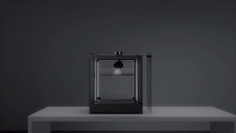
In the dynamic engineering world, where rapid iteration and efficient production are paramount, new technologies that accelerate design and manufacturing processes hold immense value. Enter Hyper FFF (Fused Filament Fabrication), a cutting-edge way to 3D print developed by Raise3D. Hyper FFF is a groundbreaking 3D printing system engineered for unparalleled efficiency and performance, offering engineering professionals new advantages in prototyping and small-batch production.
Unleashing Speed and Quality:
At the core of Rasie3D’s Hyper FFF lies its ability to achieve unparalleled print speeds, boasting 100% quality and 300% productivity on its website, while maintaining exceptional part quality. By leveraging advanced hardware, sophisticated feedback loops, specialized filaments, and an active vibration cancellation algorithm, Hyper FFF enables engineers to push the boundaries of speed and efficiency in additive manufacturing. With Hyper FFF, design iterations can be completed in record time, leading to faster product development cycles and increased engineering productivity.
Accelerating Design Iterations for Engineers:
For engineers, design iterations are a critical aspect of the development process. Hyper FFF’s remarkable speed allows engineers to rapidly iterate and refine their designs, facilitating quicker testing, validation, and optimization. The accelerated design process empowers engineers to explore multiple design options, evaluate their performance, and make informed decisions faster than ever before. By shortening the design cycle, designers gain a competitive edge, allowing them to bring innovative products to market more quickly and stay ahead of their competitors.
Reduced Print Time for Engineering Applications:
Hyper FFF’s high-speed capabilities significantly reduce print times for engineering applications. Complex prototypes and small-batch production runs that previously required hours or even days to print can now be produced in substantially less time. This accelerated production process enables engineers to meet tight project deadlines, ensuring timely delivery and increased client satisfaction. With Hyper FFF, engineers can optimize their workflows, enhance productivity, and drive innovation forward.
Enhanced Success Rate and Quality Control:
Hyper FFF technology integrates advanced features, like its active vibration cancellation algorithm and optimized filaments, to improve the rate of successful prints and ensure consistent quality in engineering applications. By mitigating vibrations and minimizing printing failures, Hyper FFF delivers reliable results and reduces material waste. Engineers can achieve a higher percentage of successful prints, leading to improved productivity and cost-effectiveness. Hyper FFF empowers engineers with the confidence that their parts will meet the stringent quality standards required in demanding engineering applications.
Shortened Lead Time for Engineering Parts:
Minimizing lead times is crucial in engineering to maintain project schedules and meet client demands. Hyper FFF’s exceptional speed and quality both directly contribute to shortened lead times for individual or even small-batch printed parts. By harnessing the power of Hyper FFF, engineers can manufacture components faster, accelerating the overall production process. This agility ensures timely project completion, minimizing delays, and improving customer satisfaction. With Hyper FFF, engineering firms gain a competitive advantage by delivering high-quality parts in less time.
Embracing In-House Supply for Engineering Applications:
Hyper FFF’s capabilities make it an ideal solution for in-house supply production in the engineering industry. By leveraging Hyper FFF technology, engineering firms can reduce reliance on external suppliers, streamline their supply chains, and gain greater control over production timelines. With the ability to produce parts on demand, engineers can optimize inventory management, reduce costs, and respond swiftly to changing project requirements. Hyper FFF enables engineering professionals to drive innovation and improve the efficiency of their in-house production processes.
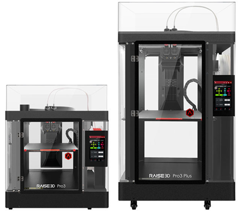
Currently, Hyper FFF technology is primarily available for the Pro3 Series printers. The Pro3 Series printers are specifically engineered to leverage the full potential of Hyper FFF, providing exceptional speed and uncompromising quality. Learn more about the Pro3 series on our product page here. Hyper FFF technology is a game-changer for engineers involved in prototyping and small-batch production. By offering unparalleled speed, uncompromising quality, and increased efficiency, Hyper FFF empowers engineering professionals to accelerate design iterations, reduce lead times, and enhance overall productivity.
Any questions? Need help? Ask one of our experts.
Whether you’re ready to get started or just have a few more questions, you can contact us toll-free:
As the leading software suite for 3D modeling and design, SOLIDWORKS revolutionizes the way engineers and designers bring their ideas to life. Whether you’re a beginner looking to kickstart your SOLIDWORKS journey or an experienced professional seeking to enhance your skillset, training and certification play a crucial role in mastering this powerful tool. In this blog, we will explore the benefits of SOLIDWORKS training and certification, as well as provide valuable insights and Xpert tips to help you navigate the network of knowledge bases and learning pathways and get the most out of your trusted SOLIDWORKS software.
The Power of SOLIDWORKS Training
SOLIDWORKS training programs offer a structured approach to learning the software’s functionalities, tools, and workflows. These programs cater to individuals at all skill levels, from beginners to advanced users. By enrolling in SOLIDWORKS training, you gain access to expert instructors who guide you through hands-on exercises, real-world projects, and best practices. This immersive learning experience allows you to grasp SOLIDWORKS’ vast capabilities quickly and build a strong foundation for continued growth.
Benefits of SOLIDWORKS Certification
Earning a SOLIDWORKS certification validates your expertise and proficiency in using the software. It demonstrates your commitment to professional development and sets you apart in a competitive job market.
Industry recognition: Employers recognize SOLIDWORKS certifications as a mark of excellence and expertise, giving you a competitive edge when seeking job opportunities or advancements in your career.
Enhanced skills and efficiency: The certification process challenges you to master various aspects of SOLIDWORKS, expanding your knowledge and proficiency. This newfound expertise enables you to work faster and more efficiently, saving time, increasing productivity, and streamlining your design routines.
Network and community: Becoming certified connects you with a vibrant community of SOLIDWORKS professionals, providing opportunities for networking, knowledge sharing, and collaboration.
Navigating the Certification Path
SOLIDWORKS certifications are offered at different levels, allowing individuals to progress from entry-level to advanced designations. Understanding the certification path is essential for setting clear goals and planning your learning journey.
As a Certified SOLIDWORKS Training Center, SolidXperts offers training for all topics the SOLIDWORKS certifications cover, from SOLIDWORKS general training and performance optimization to tool-specific lessons. Plus, our courses discuss more than just the CAD training you’ll need, but also include information about exam prerequisites, formats, and tips for success at each level. Reach out to our certified trainers today and we’ll help you create the learning pathway that best suits how you design.
Certified SOLIDWORKS Associate (CSWA):
The Certified SOLIDWORKS Associate (CSWA) certification serves as the entry-level credential for SOLIDWORKS users. It validates your fundamental understanding of SOLIDWORKS tools and functionality. This exam option is a great place for graduating students to start their 3D certification journey. To prepare for the CSWA exam, you can follow these steps:
1 – Familiarize yourself with SOLIDWORKS: Begin by getting acquainted with the SOLIDWORKS user interface, basic sketching tools, part modeling techniques, assemblies, and drawings. This foundational knowledge forms the core of the CSWA exam.
2 – Enroll in SOLIDWORKS training courses: Check out our full catalog of training to find the right courses that will empower you to master SOLIDWORKS.
3 – Practice with sample exams: SOLIDWORKS provides sample exams that closely mimic the format and difficulty level of the CSWA certification. Practice these exams to familiarize yourself with the question types and identify areas where you need improvement.
Certified SOLIDWORKS Professional (CSWP):
The Certified SOLIDWORKS Professional (CSWP) certification is the next level after CSWA, focusing on more advanced modeling techniques, assemblies, and drawing functionalities.
1 – Gain practical experience: Build your proficiency by working on real-world projects that require complex part modeling, assembly design, and drawing creation. Practical experience enhances your understanding of SOLIDWORKS and prepares you for the challenges faced in the CSWP exam. This will also give you the opportunity to put your CSWA to work!
2 – Advanced training courses: Advanced SOLIDWORKS training courses cover the topics tested in the CSWP exam. These courses delve into advanced sketching techniques, surfacing, sheet metal design, and complex assemblies.
3 – Practice makes perfect: SOLIDWORKS provides sample exams and tutorials specifically designed for CSWP preparation. Use these resources to practice and reinforce your knowledge of advanced modeling techniques and assemblies.
It’s worth noting, though we recommend taking the CSWA before the CSWP, it is not a prerequisite. However, you must take the CSWP before taking the CSWE.
Certified SOLIDWORKS Advanced Professional (CSWPA)
In addition to the core certifications, SOLIDWORKS offers a range of specialty certifications that allow you to showcase your expertise in specific areas. These specialty certifications are designed to validate your proficiency in specialized skills, expanding your knowledge and making you a sought-after professional in your chosen field. Here are a few examples:
Sheet Metal (CSWPA-SM)
The CSWPA-SM exam assesses your proficiency in creating complex sheet metal designs using SOLIDWORKS. This exam tests your ability to create and modify sheet metal parts, apply bend allowances and reliefs, generate flat patterns, and create detailed drawings for manufacturing.
Mold Making (CSWPA-MM)
The CSWPA-MM exam assesses your proficiency in mold design using SOLIDWORKS. This exam tests your knowledge and skills in creating core and cavity components, applying draft angles, designing parting lines, and generating mold bases and inserts.
Surfacing (CSWPA-SU)
The CSWPA-SU exam evaluates your proficiency in advanced surfacing techniques using SOLIDWORKS. This exam tests your skills in creating complex surface geometry, utilizing surfacing tools, and applying advanced surfacing features.
Drawing Tools (CSWPA-DT)
The CSWPA-DT exam assesses your proficiency in utilizing SOLIDWORKS drawing tools to create detailed engineering drawings. This exam evaluates your skills in creating and modifying drawing views, applying annotations, generating bills of materials (BOM), and utilizing advanced drawing tools.
Weldments (CSWPA-WD)
The CSWPA-WD exam evaluates your proficiency in using SOLIDWORKS Weldments to design and document welded structures. This exam tests your skills in creating and modifying structural members, generating cut lists, and creating detailed weldment drawings.
…and more!
Certified SOLIDWORKS Expert (CSWE):
The Certified SOLIDWORKS Expert (CSWE) certification is the highest level of achievement in SOLIDWORKS. It validates your comprehensive knowledge and ability to solve complex design challenges. In order to qualify to take the CSWE you must pass the CSWP as well as 4 additional CSWPA certifications. The CSWE exam covers a wide range of advanced topics, so be prepared with:
1 – Extensive hands-on experience: Accumulate extensive hands-on experience by working on complex projects and pushing the limits of SOLIDWORKS. Engage in challenging design scenarios that require advanced modeling, surfacing, and assembly techniques.
2 – Advanced training courses and workshops: Seek advanced training courses and workshops that focus on the topics covered in the CSWE exam. These courses often cover advanced surfacing, advanced assembly techniques, and simulation.
3 – Independent study and research: Conduct independent study and research to explore advanced SOLIDWORKS functionalities beyond what is covered in training courses. Experiment with advanced surfacing, advanced assembly configurations, and optimization techniques.
Conclusion
SOLIDWORKS certification exams can be challenging, but with the right preparation, you can increase your chances of success. SOLIDWORKS training and certifications are essential tools for unlocking your full potential as a designer or engineer. The knowledge and expertise gained through these programs can propel your career to new heights, opening doors to exciting opportunities and fostering limitless innovation. Whether you’re a recent graduate, an aspiring designer, or an experienced professional, the journey to mastering SOLIDWORKS begins with training and certification.
To explore the full SOLIDWORKS certification program, click here.
For more information about our training programs, custom training options, or how you can start your journey to SOLIDWORKS certification, contact the Xperts.
Any questions? Need help? Ask one of our experts.
Whether you’re ready to get started or just have a few more questions, you can contact us toll-free:
At the forefront of CAD innovation and engineering design quality of life, the 3DEXPERIENCE platform is constantly looking for ways to improve how the world’s engineers and product designers work. From improving their options for browser-based 3D modeling to adding new, more accessible tools and collaboration opportunities, the 3DEXPERIENCE platform adds new features as often as the world starts a new design! In this blog, we’ll discuss some of the most recent upgrades, improvements, and additions to the browser-based roles on the 3DEXPERIENCE platform to see how both designers and non-CAD users, worldwide, can benefit and enjoy a more accessible, more fluid daily design and product development routine.
Without further ado, let’s dive into the R2023x FD02 release.
1 . User Experience Quality-of-Life Upgrades
New Default Dashboard
Now, you can access all your roles in one convenient location – the SOLIDWORKS Creator Home dashboard. This dashboard is designed to help keep you organized and reduce screen clutter, allowing you to quickly access your 3DEXPERIENCE roles.
Get easy access to all your roles in one place.
System Status Menu
Enhance system performance and accurately track issues with the new System Status menu. This menu allows you to easily check the status of your network and server connections, so you can quickly identify any underlying problems that may be impacting performance.
Ensure a smooth connection and a successful design experience before you start any project.
Design in the Context of HomeByMe in 3D Creator
You can now take advantage of 3D Creator’s parametric capabilities and test for fit, function, and aesthetics when bringing your HomeByMe designs into the environment. HomeByMe, a free home design and furnishings solution by Dassault Systèmes, allows you to measure, reference, and mate to geometry in one place, ensuring your design fits your specifications. Easily share your 3D Creator models back to the HomeByMe community.
Design in a more realistic, life-like setting, and take advantage of parametric capabilities.
Selective Save
With the Selective Save feature, you can improve your collaborative workflow by saving parts of an assembly without interruption. You can quickly identify which components are locked, deselect them, and save only the components that you are currently working on. This eliminates the need to ask someone to unlock a file.
Work more efficiently and without interruption.
Lock Status and Unlock Requests
With the latest tools, you can quickly and easily identify which elements are locked and by whom, and then instantly send unlock requests directly to the right people in real-time. No more waiting for someone to unlock a file.
Collaborate seamlessly, knowing exactly which components are blocked and who to contact for immediate access.
Sketch Pattern
The Sketch Pattern command now offers increased control and flexibility when creating patterns with the new Skip Instance checkbox. This is a helpful tool when you don’t want certain instances of the pattern to be created in overlapping or whole areas. With the Skip Instance feature, you can quickly add or remove instances from your pattern without disrupting the overall pattern.
It’s now much easier to create the exact pattern you need for your design.
Hide/Show Options in Measured Command
The Measure command now offers added control and time-saving features with the Hide/Show Options. These options allow you to quickly capture measurements related to internal and hidden components that are located behind other geometry, so you don’t have to leave the Measure command to get the measurements you need.
With the Hide/Show Options, you can save time and have more control over your measurements.
Volumetric Section View
By using Volumetric Section View, you can create a bounding box to divide your design into sections, allowing you to view the internal components without being distracted by additional elements. With this view, you can focus solely on the task at hand, giving you the ability to gain a better understanding of your design.
Easily cut through the clutter and gain clarity in your designs.
2 . Manufacturing Definitions
Section Views
With a new 3D view type, you can easily create professional representations of internal features and dimensions for downstream communication. This makes it easier to define manufacturing information for internal component geometry.
Capture design intent and internal details of complex components more clearly.
Bent Leader Option
You can now customize how you display your drawings with the new bent leader option in Manufacturing Definition Creator. This feature allows you to create annotations with bent leaders that meet ASME and ISO standards for radius and diameter dimensions, giving you more control over the look of your drawings.
Be confident that all your drawings are compliant with industry requirements.
STEP A242 Export
You can now use 3DPlay to share, view, and mark up STEP A242 files for downstream communication and manufacturing. This format provides the industry-supported model-based definition (MBD) workflows.
Export 3D annotations more efficiently.
3 . Freeform Design
Align Vertices Command
The Align Vertices command has been updated. Now, when using shift-select, the first two entities you select will define the alignment axis for all the remaining points.
Specify vertices for alignment more easily.
Bend and Flex Tool
When using the Flex tool, the robot manipulator and range manipulator are now offset from one another, making them easier to use. Additionally, the Bend tool now offers a Limit Bend option that allows you to ensure the deformation of a specific design region without bending the region beyond the manipulator. With this new option, you can easily control the exact shape and form of your design.
Make your design intent clearer and gain increased control.
Improved Copy/Paste
With improved Copy and Paste, placing a copied instance of a subdivision (Sub-D) body is easier than ever. When you Copy and Paste, a preview of the new instance appears in yellow, allowing you to accurately locate it in the desired position. You also have the option to scale and flip the instance.
Create complex Sub-D geometry faster and more easily.
Reflect Command
Creating a mirrored instance of an existing subdivision body is now even easier. Simply duplicate the existing body and use the mirror tool to flip the object along the desired axis. This will create a mirrored instance of the original body which can be modified independently of the original.
Easily create a mirrored instance of a subdivision body.
Crease Command
Save time with the new and improved Crease Command! When you apply a crease, the affected entities will remain selected, allowing for further modifications without having to reselect them.
Save clicks and streamline crease creation.
4 . Sheet Metal Design
Enhanced Workflows and Mini Dialogs for Custom Walls
The Wall on Edge feature includes enhanced workflows and mini-dialogs that provide quick access to the sketch option and help to streamline the creation of custom walls and flanges. The workflow is shorter than before and the mini-dialogs are user-friendly, making it easier to use on smaller devices such as mobile phones and tablets.
Create custom non-rectangular walls and flanges quickly and easily with the new Wall on Edge feature.
5 . Structure Design
Machine Learning for End Cap and Plate Placement
With the Design Assistant Selection capabilities, you will get suggestions for multiple end cap or plate placements. Simply click on one of the endcaps and the Design Assistant will automatically populate a suggestion for the other endcaps or plates and propagate them for you.
Reduce time spent on manual work by quickly placing multiple end caps or plates.
Find out more
Whether it’s communicating with colleagues or outside stakeholders, trying to add tools to a design more efficiently, encouraging experimentation with easy-to-use features, or just making your everyday designing more enjoyable, the 3DEXPEREINCE platform’s browser-based roles seek to make your daily design routines easier and more fluid, so you can focus on innovation.
At SolidXperts, we pride ourselves on our proven ability to help our clients optimize their design and manufacturing processes through the use of modern software solutions. As a trusted SOLIDWORKS, 3DEXPERIENCE, and 3D design service provider with more than 25 years of experience, our Xpert teams enable our clients to design products faster and more efficiently, empowering them to stay competitive in ever-evolving industries.
Recently, we’ve had the opportunity to work with Beaubois, a client in the architectural millwork industry, who was looking to transition from Solid Edge to SOLIDWORKS with the SWOOD add-on. In this post, we’ll share how we helped this client achieve their goals and improve their operations.
Step 1: Complete Process Diagnosis
Woodworking and architecture projects require a great deal of precision and expertise to create beautiful and long-lasting designs. To accomplish this, it’s important to use the right tools and software.
As a Quebec-based company that specializes in custom architectural woodwork, Beaubois aims to push boundaries and challenge the expected norms of the woodworking industry without sacrificing high standards and quality designs. In order to keep up with their unique customer requests and an increasingly intricate digital design landscape, they needed to take their design processes to a higher level of CAD and CNC machine communication.
To empower Beaubois’s 3D creative journey and support their long-term goals, our first step was to conduct a comprehensive diagnosis of our client’s existing design and manufacturing processes. We wanted to identify any inefficiencies or areas where improvements could be made. This process included an in-depth analysis of their CAD data, production workflows, and automation processes.
Step 2: Pilot Project Implementation
After the diagnosis phase, we moved to the pilot project implementation stage. We worked closely with a small team of Beaubois employees to test the SOLIDWORKS software and the SWOOD add-on in a real-world scenario. The pilot project allowed us to identify any potential issues and make necessary adjustments before a full-scale deployment.
Moving from Solid Edge to SOLIDWORKS can be an intimidating prospect. Even with a perfect solution, it can be difficult to onboard a full team quickly and cost-effectively while avoiding expensive downtime. For Beaubois, SOLIDWORKS offers superior CAD collaboration capabilities and a more intuitive user interface, along with improved 2D and 3D functionality.
Our team of Xperts helped onboard their design team to the SWOOD add-in, which provides a library of woodworking components, tools for designing 3D assemblies, the ability to create 3D renderings and presentations, and much more that allowed them to streamline their processes. The add-in also includes tools for estimating material costs and calculating production times, helping companies better manage their projects. With the SWOOD add-in, Beaubois can now design high-quality woodwork projects faster and more easily. Furthermore, SOLIDWORKS and SWOOD empower them to generate accurate and detailed toolpaths for their CNC machines.
Step 3: Global Deployment and Change Management
Following the successful pilot project, we helped the client roll out SOLIDWORKS with SWOOD across their entire organization. We provided extensive training and support to ensure a smooth transition and minimize any potential disruption to their operations. We also assisted with change management to help the client’s employees adapt to the new software and processes.
As Beaubois transitioned to SOLIDWORKS and SWOOD, the investment in training and infrastructure was essential to ensure a successful transition and maximize the rewards of better design and fabrication processes.
Step 4: Improved Results
Our work with this client resulted in several key improvements to their design and manufacturing processes. With SOLIDWORKS and SWOOD, they were able to optimize their CAD data for use with their factory robots, leading to faster and more efficient production. Additionally, the SWOOD add-on allowed them to automate many of their manufacturing processes, further improving efficiency and reducing errors.
Thanks to SolidXperts’ help, Beaubois has been able to transition to SWOOD for design and fabrication, resulting in enhanced communication and collaboration among staff, customers, and suppliers. This streamlining of the design process has saved Beaubois both time and money, while also allowing them to create products of the highest quality that exceed customer expectations. SolidXperts’ guidance and support during the transition enabled Beaubois to significantly increase their output and cost efficiency, while simultaneously creating more productive, more easily managed workflows.
Conclusion
We’re proud of the work we did with this client, and we believe it can serve as an inspiration to other businesses looking to improve their operations. To highlight our work, we created a video testimonial featuring the client discussing their experience working with us. In the video, they describe how our team helped them achieve their goals and improve their processes. Check it out!
We are passionate about helping our clients achieve their goals through the use of modern software solutions. Our work with this client in the architectural millwork industry is a great example of how we can help businesses improve their operations and achieve success. If you’re interested in learning more about our services or how we can help you optimize your processes, please contact us today.
Montreal, Quebec – SolidXperts, a leading provider of Dassault Systèmes SOLIDWORKS and 3DEXPERIENCE software solutions, as well as additive manufacturing technology, has announced its acquisition of Instadesign Group’s CAD division, a company in the same industry, as well as a strategic partnership with their Technical Service Division. The acquisition and partnership are expected to significantly expand SolidXperts’ customer base and enhance its product and service offerings.
“The addition of this division to our family of companies is an exciting step forward for our organization,” said Alex Habrich, Founder and CEO of SolidXperts. “Not only does it enable us to better serve our existing customers, but via our partnership with Instadesign Group’s Technical Division it also brings on board a team of talented professionals who share our commitment to excellence in the Engineering field. We are also proud to be the 5th largest SOLIDWORKS reseller in North America.”
SolidXperts has a long-standing reputation for delivering innovative and high-quality products and services that exceed customer expectations. With the acquisition of Instadesign’s CAD Division and association with its Technical Service division the company will be able to leverage its expertise and resources to drive even greater success in the marketplace.
“We are confident that this acquisition will enable us to achieve even greater growth and success in the years ahead,” said Alex Habrich. “We are excited to welcome Instadesign Group’s CAD Division to the SolidXperts family and look forward to working together to deliver exceptional value to our customers.”
The acquisition is expected to close on March 31st, 2023, pending regulatory approval. Financial details of the transaction were not disclosed.
For more information about SolidXperts and its products/services, please visit www.SolidXperts.com
Any questions? Need help? Ask one of our experts.
Whether you’re ready to get started or just have a few more questions, you can contact us toll-free:
Using the finite element analysis (FEA) tools available in SOLIDWORKS can help engineers, designers, and other professionals quickly and accurately analyze the performance of their 3D designs. FEA is a powerful toolkit for predicting the behavior of structural components and assemblies across a wide range of conditions. It can help to reduce the number of physical prototypes that must be produced before a design is finalized.
To get started with your SOLIDWORKS tools, you’ll first need to understand the basics of FEA and how it can be used. FEA is a computational method that uses mathematical equations to simulate the behavior of a structure or component under different conditions. The equations are used to determine how the component or assembly will react to various forces and environmental factors such as temperature, vibration, and pressure.
To begin, you must open the SOLIDWORKS Simulation application from the Tools menu. This will provide the user interface for setting up your FEA analysis.
The first step is to define the type of analysis that you want to perform. You can choose from a variety of analysis types, such as linear static, non-linear static, modal, and fatigue. For each type of analysis, you’ll need to define the boundary conditions, loads, and material properties.
Once you’ve defined the analysis type and boundary conditions, you can then set up the mesh. The mesh is a grid of elements that are used to model the behavior of the component. The number of elements and their size will depend on the accuracy that you need for your analysis. A higher number of smaller elements will result in a more accurate result but will take longer and more computing power to complete.
Once the mesh is set up, you can then run the analysis. The results of the analysis can be visualized in the form of graphs, tables, and animations. These results can help you to quickly and accurately understand the behavior of your design under different conditions.
Using the FEA tools available in SOLIDWORKS can be a powerful way to reduce the time and costs associated with prototyping and testing. By quickly and accurately analyzing the behavior of a design, you can reduce the number of physical prototypes that need to be produced and tested before a design is finalized.
Any questions? Need help? Ask one of our experts.
Whether you’re ready to get started or just have a few more questions, you can contact us toll-free: