Onyx GF: When Color Becomes a Function in 3D Printing

BLOG

Onyx GF: When Color Becomes a Function in 3D Printing

[techtips_featured_image_shortcode]

In an industrial environment, color is rarely chosen for aesthetic reasons alone.

A red tool, a blue jig, or a green part can instantly communicate information: which machine the tool belongs to, which vehicle model it is intended for, where it should be used, or which operation needs to be performed.

This use of color is part of a broader visual management approach, particularly common in production environments that apply Lean Manufacturing principles.

The idea is simple: if information can be understood at a glance, no one needs to search for it.

This is precisely where 3D printing takes on a new dimension with the arrival of Onyx GF, Markforged’s new glass fiber-reinforced nylon, available in several colors.

Color as a Production Tool

Using colors to quickly identify tools or equipment is nothing new.

For example, in the aerospace industry, for example, precision fastener manufacturer M.S. Aerospace uses interchangeable aluminum trays that are color-coded according to the dimensions of the parts they are designed to hold [1]. The goal is not to make the shop floor more visually appealing: color simply helps operators identify the right equipment more quickly.

A similar approach can be found at PalletOne, an American pallet manufacturer. As part of its Lean initiative, the company assigned each machine its own set of color-coded tools. A blue tool placed near a green machine immediately indicates that it is probably out of place. This organization improves visibility and makes tools easier to track [2].

In both cases, color becomes a form of information.

As a result, that information can deliver very tangible value: reducing errors, accelerating an operation, or simply preventing time from being wasted searching for the right tool.

5S: Making the Workplace Visual

More broadly, this approach fits directly into the 5S philosophy, a workplace organization method associated with Lean Manufacturing and visual control [3].

The five steps are often presented by their Japanese names, English translations, and French equivalents:

Japanese English
Seiri Sort
Seiton Set in Order
Seiso Shine
Seiketsu Standardize
Shitsuke Sustain
  • Seiri means eliminating what is not necessary.
  • Seiton means organizing what remains so that every item has a clearly defined place.
  • Seiso adds cleaning and workplace inspection.
  • Seiketsu turns this organization into a standard.
  • Finally, Shitsuke means sustaining these practices over time.

However, the principle behind 5S goes beyond simply keeping a workshop clean. It is about creating an environment where abnormalities and errors become visible.

That is where color becomes particularly valuable.

If color makes it possible to identify a tool immediately, it can become part of the visual control system itself.

When a Few Millimeters Make All the Difference

A recent example illustrates this approach particularly well.

At Subaru of Indiana Automotive (SIA), several vehicle models are produced on the same line. Some of the jigs used for these different models can have very similar geometries, with differences of only a few millimeters.

In an environment where tools are handled and reused many times during a shift, selecting the wrong jig can lead to an error, rework, or lost time.

To address this challenge, SIA integrated color coding into its tooling so that the correct jig could be identified immediately.

The problem was that ABS-printed parts could provide the desired color, but not the durability required for repeated use on an automotive production line.

This is where Onyx GF comes into its own.

SIA uses colored Onyx GF tooling for applications ranging from positioning jigs to more robust assembly fixtures. Color differentiates the tools, while the material maintains the mechanical performance required for production use.

As a result, color is therefore no longer a finish added after manufacturing.

It becomes part of the part’s function.

Onyx GF: Where Color Meets Industrial 3D Printing

With this challenge in mind, Markforged developed Onyx GF.

Introduced in 2026, Onyx GF is a short glass fiber-reinforced nylon available in six colors: red, yellow, blue, green, gray, and white. The material is designed for industrial applications where color can support visual management, safety, or error prevention.

The benefits are particularly clear for jigs, fixtures, and production tooling.

In practical terms, imagine a company that uses several nearly identical jigs for different product variants.

Instead of having to read a reference engraved on each part, an operator can associate:

  • One color with a model
  • Another with an operation
  • Another with a production area
  • A color with a level of criticality

Geometry remains important, but identification becomes instantaneous.

Furthermore, this approach also aligns with the principle of poka-yoke, or mistake-proofing: using product or process design to reduce the possibility of an error occurring.

From Filament to Production Tool

In this context, one of the main advantages of 3D printing in this context is the ability to quickly produce tools tailored to a specific application.

Moreover, a jig does not need to be mass-produced to be cost-effective. A single part or a few units may already justify the use of additive manufacturing when traditional tooling would require more time or resources.

With Onyx GF, this flexibility now comes with visual information built directly into the part.

Potential applications include:

  • Assembly jigs differentiated by model
  • Fixtures identified by workstation
  • Tool holders associated with a specific machine
  • Replacement parts identified by function
  • Tooling intended for environments where FOD management is important
  • Safety components that require quick visual identification

Color can even distinguish several versions of the same part without requiring any change to its geometry.

A Color That Eliminates an Additional Step

Traditionally, when a printed part needed to be visually identified, several solutions were available: paint, labels, markings, or engraving.

These methods can work, but they add another step to the manufacturing process.

By contrast, with a colored material, the information is built directly into the part during printing.

This is particularly valuable in a production environment, where every additional step can become a source of variation or maintenance.

The approach is even more relevant when the part is handled regularly. Color embedded in the material does not depend on a label that could peel off or paint that could wear away.

What If the Part Also Needs to Be Strong?

This is where the comparison with traditional colored plastics becomes interesting.

However, color alone is not enough for an industrial application. A production jig must withstand handling, repeated contact, and the specific stresses of its environment.

Onyx GF uses a nylon matrix reinforced with short glass fibers. Published data indicates a flexural strength of 88.2 MPa and a flexural modulus of 2.4 GPa. The material can also be reinforced with Continuous Carbon Fiber for applications requiring greater structural performance.

This positions Onyx GF not simply as a new way to produce colored parts, but as a material designed for functional industrial applications.

Onyx GF or Onyx?

The comparison with standard Onyx is particularly interesting.

Standard Onyx is a nylon reinforced with chopped carbon fiber. Markforged reports a flexural strength of 71 MPa and a flexural modulus of approximately 3.0 GPa for this material [4].

Property Onyx Onyx GF
Reinforcement Chopped carbon fiber Short glass fibers
Colors Black Six colors
Flexural strength 71 MPa 88.2 MPa
Flexural modulus ~3.0 GPa 2.4 GPa
Continuous fiber reinforcement Yes Yes, with Continuous Carbon Fiber
Typical applications Engineering parts and tooling Color-coded tooling, visual management, and industrial applications

Of course, these values should be compared with caution, since testing conditions and print parameters can influence the final properties of a part.

The key is therefore not to determine which material is “better,” but to choose the one that best suits the application.

In other words, Onyx remains an excellent choice when color does not provide functional value, while Onyx GF becomes particularly valuable when visual identification is part of the requirement.

What Do You Need to Print With Onyx GF?

At launch, Onyx GF is compatible with the Markforged FX10 and FX20 printers. Because the material contains glass fibers, it also requires a Plastic Hardened Nozzle.

Onyx GF can also be combined with Continuous Carbon Fiber for applications requiring greater structural strength.

However, compatibility is expected to evolve. The material has only just entered the market, and information published by Mark3D already indicates that support for additional Markforged platforms is planned in the near future.

Therefore, it will be worth following its development over the coming months.

A New Way to Think About Tooling

Ultimately, the arrival of Onyx GF illustrates an interesting trend in industrial additive manufacturing: the value of a part is not limited to its mechanical properties.

Its color, ease of identification, role in a 5S process, or ability to prevent an error can be just as important.

For a company already 3D printing its jigs and fixtures, switching to a colored material may seem like a small change.

Operationally, however, it can transform how tools are organized and used on the production floor.

And that may be the main advantage of Onyx GF: transforming color into a true function of the part without compromising the requirements of industrial 3D printing.



Lilian

Lilian Beatrix

Additive Manufacturing Specialist

X_green_halo

Any questions? Need help? Ask one of our experts.

Whether you’re ready to get started or just have a few more questions, you can contact us toll-free:


    DriveWorks: How to Automate SOLIDWORKS Design and Configurable Product Sales

    BLOG

    DriveWorks: How to Automate SOLIDWORKS Design and Configurable Product Sales

    [techtips_featured_image_shortcode]

    At a Glance

    DriveWorks helps manufacturers of configurable products turn their engineering rules into a repeatable digital process. Instead of copying an old project, renaming files, and manually modifying each model, teams enter the requirements into a form. DriveWorks then applies approved rules to generate the required deliverables.

    The product line includes three levels:

    • DriveWorksXpress to explore basic automation in SOLIDWORKS for free;
    • DriveWorks Solo to streamline and improve the design process for engineers;
    • DriveWorks Pro to deploy a product configurator and CPQ process across the company and even externally on the web.

    What Is DriveWorks?

    DriveWorks is design automation and product configuration software that is closely integrated with SOLIDWORKS. It captures product parameters, customer options, and manufacturing rules, then reuses them to create reliable variants and configurations.

    In practical terms, DriveWorks can automatically control:

    • dimensions, features, textures, materials, and even custom properties;
    • SOLIDWORKS parts, assemblies, and drawings;
    • file names and locations;
    • bills of materials and certain sales documents;
    • output formats such as PDF, DXF, DWG, STEP, or image files, depending on the edition;
    • validations, approvals, and workflow stages;
    • data exchanges with systems such as ERP, CRM, or SOLIDWORKS PDM when using DriveWorks Pro.

    The result is simple: a custom request can move more quickly from configuration to quotation, engineering, and production.

    What Types of Companies Is DriveWorks Designed For?

    DriveWorks is particularly well suited to manufacturers that offer products that are similar but rarely identical. An industrial enclosure with variable dimensions, a modular conveyor system, equipment adapted to a customer’s space, or a structure available with several options are all good examples.

    Your company could benefit from DriveWorks if you answer yes to any of these questions:

    • Do your designers often repeat the same changes in SOLIDWORKS?
    • Do you regularly create variants from previous projects?
    • Do data-entry, bill-of-materials, or drawing errors delay orders?
    • Does preparing quotes require frequent back-and-forth with engineering?
    • Do configuration rules depend mainly on the experience of a few people?
    • Would you like your sales representatives, distributors, or customers to configure a product online?

    Even one yes may reveal an automation opportunity. The right approach is to target a repetitive, well-understood product and then evaluate how much time is currently spent on each order.

    DriveWorksXpress, Solo, or Pro: Which Version Should You Choose?

    Solution

    Ideal for

    Main capabilities

    How it is used

    DriveWorksXpress

    Getting started with a first automation project Basic part and assembly automation, a simple form, and one drawing per part or assembly Included free with SOLIDWORKS

    DriveWorks Solo

    Automating the work of one designer or an engineering department Part, assembly, and drawing automation; control over file names and locations; documents such as bills of materials and quotes; and previews in SOLIDWORKS Single-user SOLIDWORKS add-in

    DriveWorks Pro

    Connecting sales, engineering, and production CPQ, web configurators, interactive 3D previews, automated documents, workflows, security, unattended generation, and enterprise integrations Modular, scalable platform

    DriveWorksXpress: A Free Entry Point

    DriveWorksXpress is included with SOLIDWORKS and can be opened from the Tools menu. It lets you capture an existing model, create a simple form, and control certain dimensions, features, or properties to generate a new variant.

    This edition is suitable for a team that wants to validate an initial use case without immediately launching a large-scale project. Its options are more limited, but it demonstrates the core DriveWorks process: capture, define rules, complete a form, and generate.

    DriveWorks Solo: Greater Control for Engineering

    DriveWorks Solo takes automation further while remaining integrated with SOLIDWORKS. It provides greater control over bills of materials, file locations, drawings, and generated documents.

    A designer can complete a guided form, select the permitted options, and generate a more complete project package. Rules reduce the risk of forgetting a property, using a noncompliant name, or selecting an impossible combination.

    DriveWorks Solo is often the right choice when the need remains primarily within the engineering department but DriveWorksXpress no longer provides enough flexibility.

    DriveWorks Pro: Company-Wide Automation

    DriveWorks Pro brings together SOLIDWORKS automation, product configuration, and CPQ. It lets you create a guided experience that is accessible in a browser, complete with dynamic forms and an interactive 3D preview of the configured product.

    The data entered can trigger the automatic creation of models, assemblies, drawings, bills of materials, and sales documents. Generation can be handled by DriveWorks Autopilot on a dedicated machine, freeing up the designer’s workstation. Some capabilities require specific DriveWorks Pro modules or licences, depending on the selected architecture.

    DriveWorks Pro also lets you organize workflows. For example, an order may require technical validation or sales approval before the production files are generated.

    How Does a CPQ Configurator Work with DriveWorks Pro?

    CPQ stands for Configure, Price, Quote. In a manufacturing environment, CPQ guides users toward a viable configuration, calculates the data needed for the quote, and prepares the deliverables required to manufacture the product.

    With DriveWorks Pro, the process can follow these steps:

    • The sales representative, distributor, or customer selects dimensions and options in a form.
    • Rules validate the compatibility of the selections and display only the relevant options.
    • An interactive 3D preview reflects the selected configuration.
    • Pricing and product data can be retrieved from the company’s systems.
    • A quote and other documents are generated.
    • Once the required approvals are complete, DriveWorks creates the order-specific SOLIDWORKS files and manufacturing data.

    This process reduces reliance on manual exchanges between sales and engineering. It also helps sales teams respond faster without promising a configuration the company cannot manufacture.

    What Documents and Files Can DriveWorks Generate?

    Depending on the edition and selected configuration, DriveWorks can produce much more than a 3D model. Possible outputs include:

    • SOLIDWORKS parts and assemblies;
    • manufacturing drawings;
    • bills of materials;
    • quotes and purchase orders;
    • Word, Excel, HTML, XML, and PDF documents;
    • manufacturing or exchange files such as DXF, DWG, STEP, and STL;
    • images for sales, approvals, or the web;
    • HTML emails with attachments.

    Outputs can be triggered at the appropriate point in the workflow. A quote can therefore be created before approval, while production files are released only after the order is confirmed.

    Why Formalize Engineering Rules?

    In many companies, essential rules live in the mind of an experienced designer. This expertise is valuable, but it becomes a risk when it is neither documented nor accessible to other teams.

    DriveWorks turns this knowledge into executable rules. This allows a company to:

    • apply the same standards to every order;
    • prevent noncompliant combinations;
    • reduce errors caused by repetitive tasks;
    • make it easier to onboard new employees;
    • preserve knowledge despite departures or changes in roles;
    • improve rules gradually as products evolve;
    • maintain business continuity despite staff shortages or departures.

    The benefits go beyond saving time. Automation also supports operational continuity and data quality.

    What Are the Main Benefits of DriveWorks Automation?

    Reduce Repetitive Tasks

    Rules can handle model copying, file renaming, dimension changes, and document preparation.

    Speed Up Quotes and Orders

    A guided form gathers the right information from the start. Teams spend less time clarifying incomplete or incompatible selections.

    Improve Consistency

    The same design, naming, and approval rules are applied to every project.

    Free Designers to Focus on Higher-Value Work

    While order-specific files are being generated, engineers and designers can work on new products, complex problems, or continuous improvement.

    Connect Departments

    With DriveWorks Pro, sales, engineering, operations, and production can use the same process while retaining access rights and approval stages suited to their responsibilities.

    How Do You Start a DriveWorks Project?

    The best first project is not necessarily the most complex product. Instead, choose a stable product family that is configured frequently and involves measurable repetitive tasks.

    A structured implementation generally includes:

    • an analysis of the current process and product variants;
    • the selection of a pilot project;
    • the preparation of SOLIDWORKS models;
    • the formalization of rules, data, and exceptions;
    • the creation of forms and documents;
    • an analysis of real-world cases, including edge configurations;
    • user training and continuous improvement.

    The Solidxperts team can support you with evaluation, architecture, integration, training, and support. The goal is to help you become self-sufficient and scale the solution as your needs evolve.

    Move from Manual Customization to a Repeatable Process

    When a product changes frequently but follows known rules, manually modifying every order eventually becomes costly. DriveWorks lets you capture those rules once and then apply them consistently to models, documents, and process stages.

    Not sure whether DriveWorksXpress, DriveWorks Solo, or DriveWorks Pro is right for you? Talk to a specialist to identify the best pilot project and estimate the automation potential of your configurable products.

    FAQ

    Does DriveWorks Replace SOLIDWORKS?

    No. DriveWorks automates and controls SOLIDWORKS models using rules and data. SOLIDWORKS remains the design tool used to create parts, assemblies, and drawings.

    Is DriveWorksXpress Free?

    Yes. DriveWorksXpress is an entry-level solution included with SOLIDWORKS. It can be launched from the Tools menu in SOLIDWORKS.

    What Is the Difference Between DriveWorks Solo and DriveWorks Pro?

    DriveWorks Solo primarily automates design work in SOLIDWORKS for an individual user or an engineering department. DriveWorks Pro adds a broader platform with a web configurator, CPQ, 3D visualization, workflows, security, unattended generation, and enterprise system integrations.

    Can DriveWorks Generate Quotes?

    Yes. DriveWorks Solo can generate documents such as quotes using templates and data. DriveWorks Pro takes this further with a CPQ process, pricing rules, approvals, customized documents, and integrations.

    Can DriveWorks Integrate with an ERP, CRM, or PDM System?

    Yes. DriveWorks Pro offers integration options for SOLIDWORKS PDM and other enterprise systems using connectors, databases, web services, exchange files, or an API. The method depends on the systems in place and the required data flow.

    Do You Need Programming Skills to Use DriveWorks?

    Experience with parametric modeling and a solid understanding of product rules are helpful. However, DriveWorks provides form and rule design tools that reduce the need to develop a custom application from scratch. Advanced integrations may require additional technical expertise.


    Alain

    Alain Provost

    Senior Technical Sales Executive

    X_green_halo

    Any questions? Need help? Ask one of our experts.

    Whether you’re ready to get started or just have a few more questions, you can contact us toll-free:

      How SOLIDWORKS Flow Simulation and Markforged Simulation Helped Optimize a Race Car Part

      BLOG

      How SOLIDWORKS Flow Simulation and Markforged Simulation Helped Optimize a Race Car Part

      [techtips_featured_image_shortcode]

      In this project, SOLIDWORKS Flow Simulation and Markforged Simulation were used to optimize a reinforcement bracket for a race car before it was manufactured. Aerodynamic simulation helped determine the loads acting on the part, while Eiger was used to optimize its print orientation, infill, and continuous carbon fiber reinforcement. The final 3D-printed part achieved a worst case safety factor of 2.18 while keeping material usage and manufacturing costs under control.

      From the Racetrack to Additive Manufacturing

      A difference in handling between the left and right sides of a race car may seem minor. At high speeds, however, it can reveal an important mechanical or aerodynamic issue.

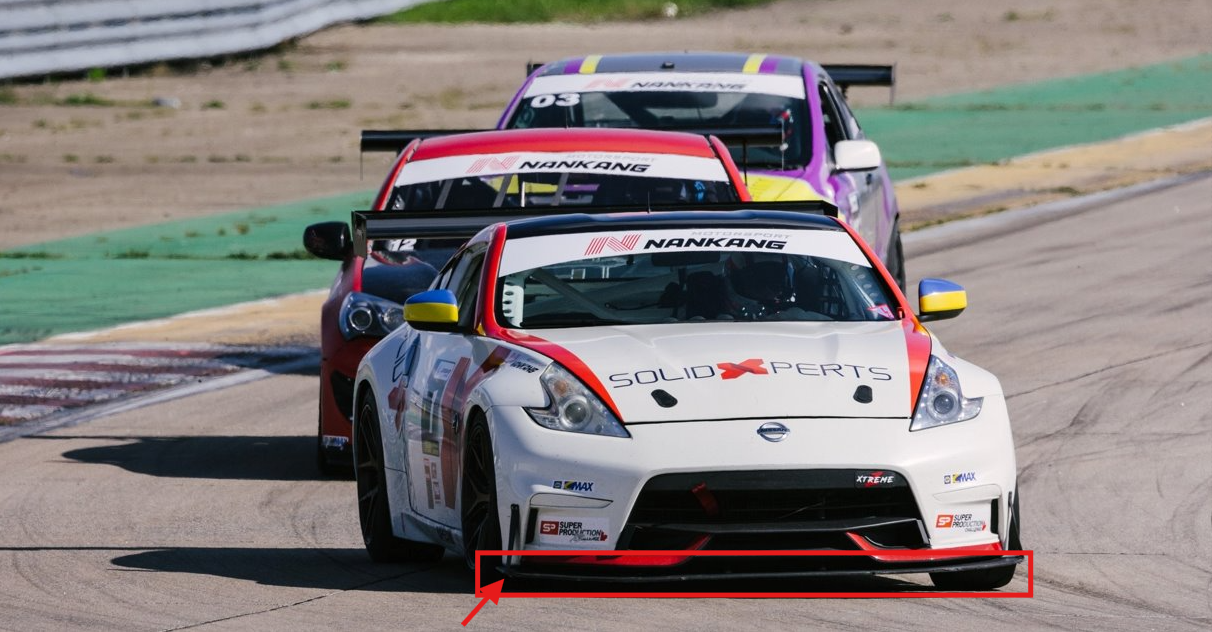
      That is exactly what happened with one of the vehicles sponsored by Solidxperts. The driver noticed a difference in how the car behaved from one side to the other. After several inspections, the team discovered that the splitter, the component located at the front and underneath the vehicle, had partially detached on one side.

      Racetrack to Additive Manufacturing

      A reinforcement bracket was needed to securely hold the splitter in place without negatively affecting the vehicle’s aerodynamics. Since only a small number of vehicles required the part, additive manufacturing offered a fast and cost-effective solution.

      The project followed three main steps:

      1. Optimize the bracket geometry using SOLIDWORKS Flow Simulation.

      2. Determine the loads that the part would need to withstand.

      3. Optimize its print orientation and manufacturing parameters using Markforged Simulation in Eiger.

      Why Simulate a Part Before 3D Printing It?

      Simulation makes it possible to evaluate multiple concepts virtually before spending time and material on physical prototypes. It can help answer practical questions such as:

      • Does the part’s shape increase aerodynamic drag?

      • Will the component withstand the expected loads?

      • Which print orientation provides the best mechanical performance?

      • Where should continuous carbon fiber be added?

      • Can the required safety factor be achieved without unnecessarily increasing cost?

      In this project, simulation created a link between design and manufacturing. The results from the fluid analysis were used to define the structural loads, and the printing parameters were then adjusted based on the stresses acting on the part.

      Step 1: Optimizing Aerodynamics with SOLIDWORKS Flow Simulation

      Defining Realistic Operating Conditions

      SOLIDWORKS Flow Simulation is directly integrated into SOLIDWORKS. Its setup tools guide users through the definition of fluids, units, boundary conditions, and simulation goals.

      To reproduce a demanding operating condition, the team simulated a total relative air speed of 300 km/h, representing a vehicle traveling at 200 km/h with a 100 km/h headwind.

      The primary objective was to measure the drag force acting on the reinforcement bracket. This value would later be used as an input load for the structural validation of the part.

      Creating an Appropriate Mesh

      The mesh divides the simulation domain into small cells where the software solves the fluid flow. Local mesh refinement can be applied around surfaces and details that have a greater influence on the results.

      A mesh preview makes it possible to review the setup before running the calculation. This is an important step, since a simulation is only as reliable as the assumptions, boundary conditions, and mesh used to represent the real-world situation.

      Evaluating the Airflow and Measuring Drag

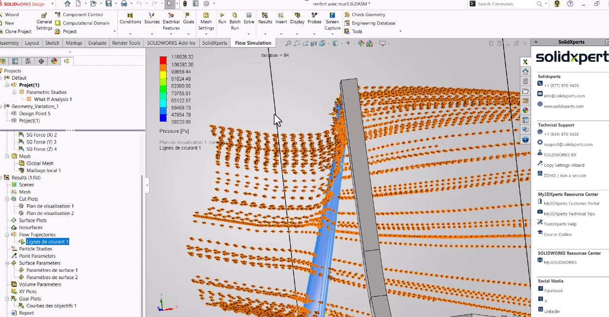
      Once the calculation was complete, flow trajectories made it possible to visually confirm how the air moved around the part. The first configuration produced a drag force of approximately 14 to 15 N.

      To maintain a conservative margin, the team also analyzed the part without considering the beneficial aerodynamic effect of the vehicle body. This more severe scenario produced approximately 20 N of drag, and this value was retained for the next stage of the project.

      Evaluating the Airflow and Measuring Drag

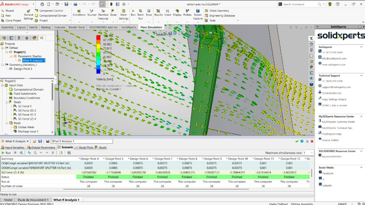
      Automating Geometry Optimization

      A design study can automatically vary several parameters, including:

      • The radius of the leading edge

      • The thickness of the part

      • Its angle

      • Other dimensions that influence the airflow

      Instead of manually modifying and recalculating each version, the software can compare multiple scenarios to identify the geometry that minimizes drag. This approach reduces the number of physical prototypes required and speeds up concept validation.

      Step 2: Turning Simulation Results into Strength Requirements

      Once the bracket geometry had been defined, the next step was to establish the design loads. Three objectives were selected:

      • Withstand an aerodynamic load of 40 N, representing the conservative 20 N drag force multiplied by a factor of two.

      • Support a vertical load of 25 N per screw, for a total of 50 N, representing the weight and forces acting on the splitter.

      • Achieve an overall safety factor greater than 2.

      These conditions were then reproduced in Eiger.

      The upper connection to the vehicle body was modeled as a fixed constraint, while the lower mounting points were represented by supports that allowed certain movements while restricting the required transverse motion.

      Automating Geometry Optimization

      Step 3: Choosing the Best Markforged Print Orientation

      Why Does Print Orientation Affect the Strength of a 3D-Printed Part?

      A 3D-printed part does not have the same mechanical properties in every direction. The material is generally weaker along the Z-axis, which corresponds to the direction in which layers are stacked, due to the nature of interlayer bonding.

      The goal is therefore to orient the part so that its weakest direction is exposed to the lowest stresses.

      Two orientations were compared in Eiger:

      Print Orientation

      Safety Factor

      Estimated Cost

      Result

      Vertical

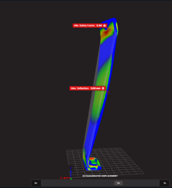
      0.94

      $10.89

      Insufficient strength

      Horizontal

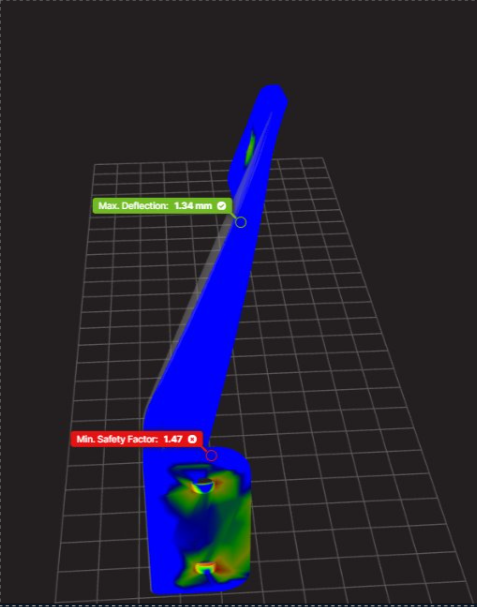
      1.47

      $11.06

      56% increase in safety factor

      The horizontal orientation increased the safety factor by 56%, while the estimated cost increased by only about 1.5%. It was therefore selected as the starting point for the final optimization.

      Why Does Print Orientation Affect the Strength of a 3D-Printed Part?

      Why Does Print Orientation Affect the Strength of a 3D-Printed Part?!

      The costs presented in this case study are specific to the project and are primarily intended to compare different configurations. Actual costs may vary depending on the material, machine, print settings, and production conditions.

      Step 4: Optimizing Infill and Continuous Carbon Fiber Reinforcement

      After selecting the print orientation, the team compared several manufacturing parameters, including:

      • Infill density and pattern

      • Number of walls

      • Number of floor and roof layers

      • Placement of continuous fiber

      • Total material usage

      Eiger’s optimization capabilities proposed a continuous carbon fiber-reinforced configuration capable of exceeding the target safety factor.

      The automatically generated configuration was then refined further. Fiber layers that were initially adjacent to one another were separated by a layer of Onyx, as the bonding between Onyx and fiber can be preferable to stacking fiber directly against fiber.

      The fiber groups were also distributed toward the upper and lower regions of the part to create a structure similar to a sandwich panel.

      This arrangement improves stiffness while placing reinforcement where it provides the greatest benefit.

      Optimizing Infill and Continuous Carbon Fiber Reinforcement

      The Result: A Part Validated Before Manufacturing

      The final configuration achieved a safety factor of 2.18, exceeding the original target of 2.

      The estimated manufacturing cost remained around $30, while still being lower than some of the configurations proposed during the optimization process.

      The workflow made it possible to develop a reinforcement bracket that met the project’s three main objectives:

      • Minimize aerodynamic impact

      • Withstand the loads experienced on the racetrack

      • Reduce both manufacturing costs and the number of physical iterations

      What Are the Benefits of Combining SOLIDWORKS and Markforged Simulation?

      Using SOLIDWORKS Flow Simulation together with Markforged Simulation creates a digital workflow that connects design, validation, and manufacturing.

      This approach makes it possible to:

      • Measure realistic loads instead of relying on arbitrary estimates

      • Quickly compare multiple geometries

      • Reduce the number of physical prototypes

      • Select a print orientation based on mechanical performance

      • Strategically place continuous fiber reinforcement

      • Balance cost, print time, and part performance

      • Accelerate the production of low-volume parts

      For automotive, industrial, and manufacturing applications, this workflow helps engineers make better decisions before the first physical part is even printed.

      From Analysis to a Production-Ready Part

      A high-performance 3D-printed part depends on more than its geometry. Its performance is also influenced by the actual loads it experiences, its print orientation, the selected material, and the placement of reinforcement.

      The experts at Solidxperts can help you integrate SOLIDWORKS Flow Simulation and Markforged solutions into your product development process. By validating concepts earlier, you can reduce iterations and manufacture parts that are better suited to their real-world operating environment.

      From Analysis to a Production-Ready Part

      A high-performance 3D-printed part depends on more than its geometry. Its performance is also influenced by the actual loads it experiences, its print orientation, the selected material, and the placement of reinforcement.

      The experts at Solidxperts can help you integrate SOLIDWORKS Flow Simulation and Markforged solutions into your product development process. By validating concepts earlier, you can reduce iterations and manufacture parts that are better suited to their real-world operating environment.

      Contact our experts to discuss your next simulation or additive manufacturing project.

      FAQ

      What Is SOLIDWORKS Flow Simulation?

      SOLIDWORKS Flow Simulation is a computational fluid dynamics, or CFD, tool integrated into SOLIDWORKS. It can be used to simulate the flow of liquids and gases, visualize flow trajectories, and calculate results such as pressure, temperature, and drag force.

      What Is Markforged Simulation in Eiger Used For?

      Markforged Simulation in Eiger is used to evaluate the mechanical performance of a part before it is printed. It makes it possible to compare print orientations, infill parameters, and reinforcement strategies in order to achieve a target level of performance while controlling manufacturing costs.

      Why Can a Horizontally Printed Part Be Stronger?

      The strength of a 3D-printed part depends on the direction of its layers. The Z-axis can be more vulnerable to interlayer separation. A horizontal orientation may place the primary loads within the plane of the printed layers, where the part can provide better mechanical performance.

      What Safety Factor Should Be Used for a 3D-Printed Part?

      The appropriate safety factor depends on the application, loads, material, operating environment, and consequences of failure. In this automotive project, the target was a safety factor greater than 2, and the final design achieved 2.18.

      Critical parts should always be validated according to the standards and operating conditions applicable to their intended use.

      Is Continuous Carbon Fiber Always Necessary?

      No. The need for continuous fiber depends on the loads acting on the part and the required level of stiffness and strength.

      Simulation can help determine whether Onyx alone is sufficient or whether continuous fiber reinforcement is required. It can also help identify where that reinforcement will provide the greatest benefit.

      Can Simulation Reduce Prototyping Costs?

      Yes. By comparing multiple geometries and printing parameters virtually, it is possible to eliminate insufficient concepts before manufacturing them.

      This can reduce material consumption, machine time, and the number of physical prototypes required during development.


      Lilian

      Lilian Beatrix

      Additive Manufacturing Specialist

      X_green_halo

      Any questions? Need help? Ask one of our experts.

      Whether you’re ready to get started or just have a few more questions, you can contact us toll-free:
        What’s New in Klietsch for SOLIDWORKS: SolidSteel, DSTV Assistant, AluFrame, and LOGIKAL

        BLOG

        What’s New in Klietsch for SOLIDWORKS: SolidSteel, DSTV Assistant, AluFrame, and LOGIKAL

        [techtips_featured_image_shortcode]

        Klietsch solutions for SOLIDWORKS are evolving to simplify the design of steel and aluminum structures, the preparation of manufacturing data, and data exchange with specialized software.

        During a webinar presented by Solidxperts with guest speaker Sebastian Klietsch, CEO of Klietsch, several enhancements were unveiled for SolidSteel parametric 8.1, DSTV Assistant 6.1, AluFrame Assistant 6.1, and LOGIKAL Interface 2.1. The updates include more automation, more flexible data management, and workflows that are better integrated with SOLIDWORKS.

        Here is an overview of the most useful new features for design and manufacturing teams.

        SolidSteel parametric 8.1: More automation for structural steel design

        SolidSteel parametric is a parametric design solution for steel structures in SOLIDWORKS. The latest version introduces several enhancements focused on productivity, standardization, and data reliability.

        Saved settings for end plates

        The parameters defined when creating an end plate can now be saved. This allows users to quickly reuse their preferred configurations when creating similar connections.

        This enhancement reduces repetitive steps and helps standardize design methods across a team.

        A bill of materials without creating drawings first

        With its SQL database, SolidSteel parametric centralizes the information associated with the components of a structure. Users can now export a bill of materials directly, including:

        • the material list;
        • cut lengths and angles;
        • the profiles used;
        • plates;
        • hardware.

        This means that drawings do not need to be created first to obtain the data required for procurement or manufacturing preparation.

        A more flexible drawing assistant

        The drawing assistant automates a significant portion of the technical documentation process. It assigns item numbers to components, applies naming rules, and generates only the requested views. Only minor adjustments or notes are needed to complete the drawings.

        The generated files are then automatically organized into folders and subfolders based on their type, such as assemblies, beams, and plates. This organization makes it easier to manage projects containing a large number of parts.

        More reliable IFC exports

        The solution supports the IFC formats used for BIM data exchange. During export, components displayed in lightweight mode can be automatically loaded in resolved mode to ensure that all required geometric information is available.

        This feature helps improve the accuracy of models shared with other project stakeholders.

        Centralized configuration for the entire team

        Paths to libraries, templates, and databases can be defined centrally. This allows companies to establish a shared environment for their designers and reduce inconsistencies between workstations.

        A more practical diagnostic mode

        Diagnostic mode allows users to identify and manage certain items directly from the SolidSteel parametric task pane. Selections are synchronized with the SOLIDWORKS FeatureManager design tree, helping users quickly identify the relevant component and make changes in the right place.

        More control over design details

        Version 8.1 also offers several technical customization options:

        • defining hole diameters using an Excel table linked to the database;
        • positioning end plates relative to a plane;
        • adding chamfers perpendicular to the bearing surface on certain reinforcement plates.

        These settings give designers more flexibility to adapt connections to their company’s standards and practices.

        DSTV Assistant 6.1: Faster preparation of NC and NC1 files

        DSTV Assistant automates the creation of manufacturing data in DSTV format from SOLIDWORKS models. It can be used with structures created in SolidSteel parametric, weldments, the SOLIDWORKS Structure System, or certain types of imported geometry, such as .STEP files.

        Better issue detection

        The tool provides clearer feedback when operations could produce problematic data. For example, it can alert users when a hole is located within a bend radius or in an area that is not well suited for machining.

        This early validation helps users correct the model before the data is sent to production.

        A quick start for exports

        Quick Start mode automatically analyzes the structure, recognizes bodies, and prepares the components for export. Users can then quickly generate NC or NC1 files, complete with quantities and profile-specific information.

        This workflow reduces the time spent manually preparing manufacturing data.

        AluFrame Assistant 6.1: Better performance for aluminum assemblies

        AluFrame Assistant simplifies the design of aluminum profile structures directly within SOLIDWORKS assemblies. The latest enhancements focus primarily on data sharing and performance for large projects.

        Databases accessible to the entire team

        Databases can now be stored on a server or shared drive. This allows users to work with the same profiles, accessories, and configurations, helping ensure design consistency.

        A level of detail suited to your needs

        A global switching function allows users to choose the level of detail for components as they are inserted. Depending on the project’s needs, models can be displayed in lightweight, standard, or highly detailed form, including fillets and chamfers.

        Teams can prioritize performance during the design phase, then enable a more detailed representation when needed.

        Automated part drawings

        AluFrame Assistant now includes an assistant for generating drawings of individual parts. This automation reduces repetitive tasks and speeds up the production of the documentation required for manufacturing.

        LOGIKAL Interface 2.1: Connecting window design with SOLIDWORKS

        LOGIKAL Interface addresses a more specialized need: exchanging data between LOGIKAL, a solution used in the design and production of windows, doors, and façades, and SOLIDWORKS.

        A bidirectional workflow

        A design started in LOGIKAL can be transferred to SOLIDWORKS using XML data to generate a complete assembly. The designer can then add more complex operations in SOLIDWORKS, such as machining features or holes, and reimport those changes into LOGIKAL.

        This process makes it possible to take advantage of the specialized capabilities of each environment without having to manually rebuild the project.

        Better data mapping

        The interface supports material mapping and the transfer of custom properties between LOGIKAL and SOLIDWORKS. Its export interface has also been redesigned to make the process more visual and easier to follow.

        Enhancements designed for a more seamless workflow

        The latest enhancements to Klietsch solutions share a common goal: reducing manual steps between design, documentation, and manufacturing.

        Whether it is generating bills of materials without drawings, quickly producing NC1 files, improving the performance of aluminum assemblies, or synchronizing fenestration projects, these tools extend the capabilities of SOLIDWORKS in industries with highly specialized production requirements.

        An x.1.1 patch was also released shortly after these versions to correct version-number detection when checking for updates.

        Want to discover Klietsch solutions for SOLIDWORKS?

        The Solidxperts team can help you determine which solution is best suited to your design methods and manufacturing needs.

        Contact our experts to learn more about SolidSteel parametric, DSTV Assistant, AluFrame Assistant, and LOGIKAL Interface, or watch the full webinar to see these new features in action.


        Alain

        Alain Provost

        Senior Technical Sales Executive

        X_green_halo

        Any questions? Need help? Ask one of our experts.

        Whether you’re ready to get started or just have a few more questions, you can contact us toll-free:
          AI in SOLIDWORKS: What’s New in FD03

          BLOG

          AI in SOLIDWORKS: What’s New in FD03

          [techtips_featured_image_shortcode]

          SOLIDWORKS AI in FD03: Meet LEO, Your New Engineering Assistant

          Artificial Intelligence in SOLIDWORKS continues to evolve at an impressive pace. While FD02 introduced several AI-powered tools, FD03 changes the experience entirely by making AI conversational.

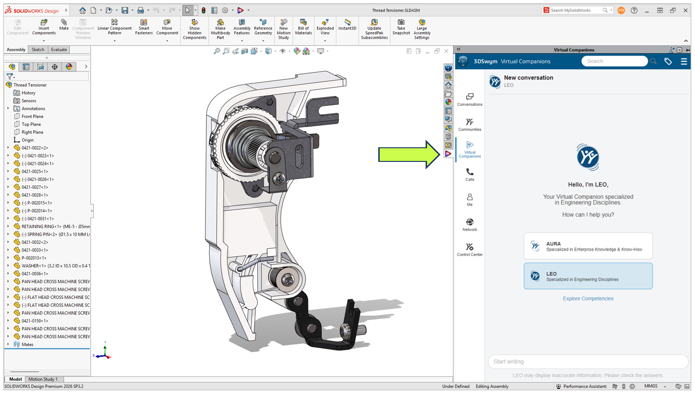
          Instead of opening separate commands or navigating multiple PropertyManagers, many of SOLIDWORKS’ newest AI capabilities are now accessed through LEO, the new SOLIDWORKS AI Virtual Companion.

          Meet LEO

          Think of LEO as an engineering assistant built directly into SOLIDWORKS. Rather than replacing engineers or making design decisions for you, it helps automate repetitive tasks, answer technical questions, and simplify complex workflows using natural language.

          Let’s take a look at everything that’s new in SOLIDWORKS FD03.

          LEO Is Becoming the New Way to Work in SOLIDWORKS

          One trend immediately stands out in FD03.

          Rather than adding another collection of disconnected AI tools, Dassault Systèmes is building a single conversational interface that ties everything together.

          Need to generate a macro?

          Ask LEO.

          Need to simplify an assembly?

          Ask LEO.

          Need to create a drawing?

          Ask LEO.

          Ask LEO.

          Instead of memorizing commands or digging through menus, you’re increasingly able to describe what you want using plain language.

          This isn’t about replacing engineering expertise. It’s about reducing the number of clicks between an idea and the result.

          Smarter CAD Editing with Intent to CAD

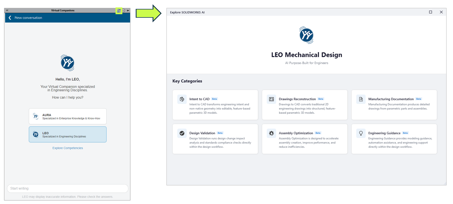
          One of the biggest improvements in FD03 is the continued evolution of Intent to CAD.

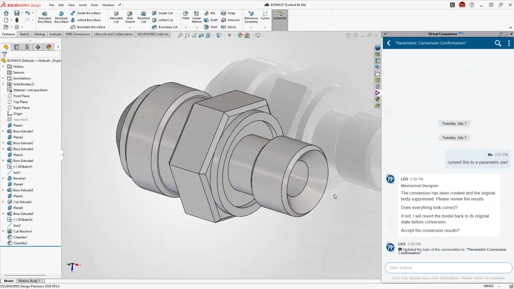
          The BREP to Parametric CAD capability introduced in FD02 is now integrated directly into LEO.

          Imported STEP and IGES files are often nothing more than non-parametric geometry, making them difficult to modify without manually rebuilding features.

          Now, simply ask LEO to convert imported geometry into an editable feature-based SOLIDWORKS model.

          This is particularly useful for:

          • Reverse engineering projects

          • Supplier CAD

          • Customer-supplied models

          • Legacy CAD data

          Instead of rebuilding models from scratch, engineers can begin making design changes almost immediately.

          Smarter CAD Editing with Intent to CAD

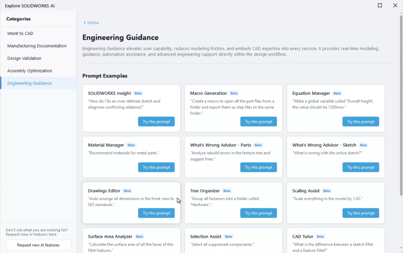
          Engineering Guidance Gets Much Smarter

          FD03 dramatically expands the number of engineering tasks LEO can assist with.

          Rather than acting like a search tool, LEO now becomes an active design assistant throughout the modeling process.

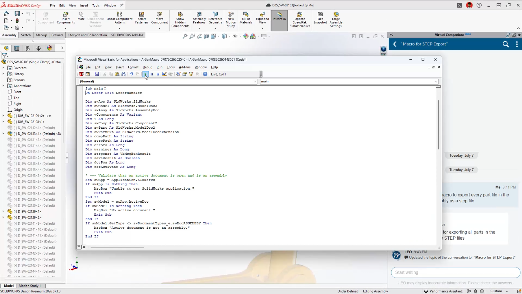
          Generate SOLIDWORKS Macros

          Automation has traditionally required knowledge of VBA programming.

          Now you simply describe the task you’d like to automate.

          Examples include:

          • Rename every configuration

          • Export every drawing sheet as a PDF

          • Rename selected files

          • Batch update custom properties

          LEO generates the VBA macro automatically and opens it directly in the editor, where you remain in complete control before running it.

          For many users, this will be their first practical introduction to SOLIDWORKS automation.

          Generate SOLIDWORKS Macros

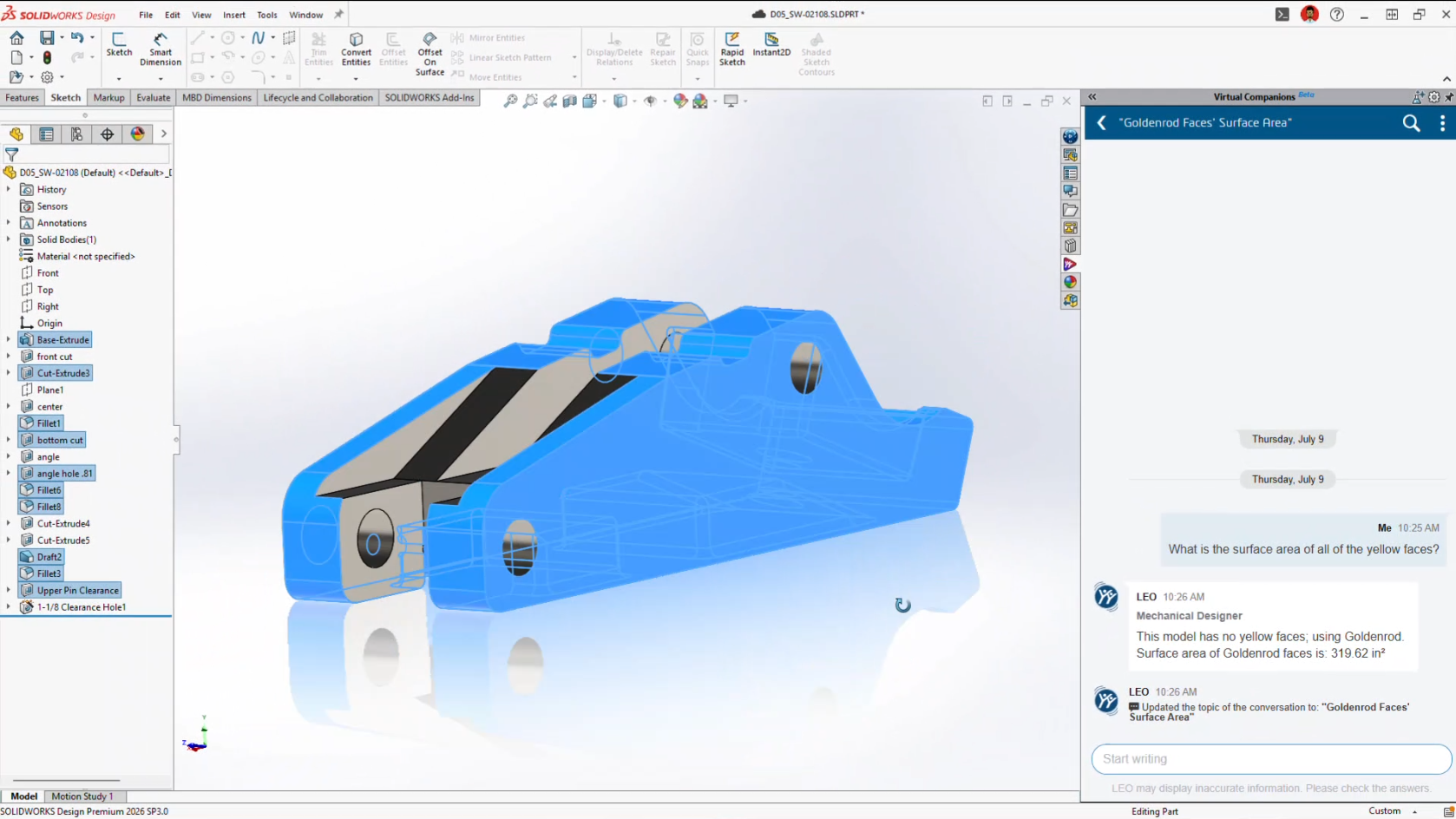
          Surface Area Reports

          Need to know how much paint or coating a model requires?

          Rather than manually measuring geometry, LEO can calculate:

          • Entire part surface area

          • Selected bodies

          • Individual faces

          • Face groups by colour

          It’s a small feature that could save a surprising amount of time in manufacturing workflows.

          Surface Area Reports

          Scale Assist

          Scaling parts has always been possible.

          Scaling them while keeping dimensions meaningful has been another story.

          Scale Assist regenerates dimensions after resizing so drawings continue reflecting the actual model dimensions instead of scaled values.

          It’s particularly useful when adapting existing designs into different product sizes.

          Natural Language Selection

          Anyone who’s spent time selecting dozens, or hundreds, of faces knows how tedious it can become.

          Now you can simply tell LEO what you need.

          Examples include:

          Select every red face.

          Select all visible sheet metal bodies.

          Select all cylindrical faces.

          Less clicking.

          Fewer mistakes.

          Faster workflows.

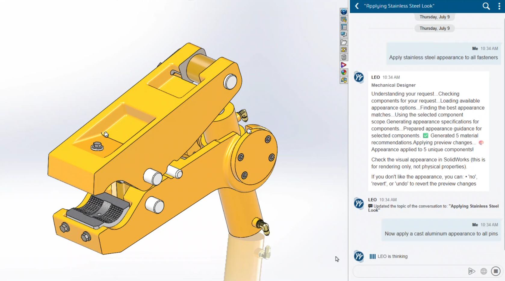
          Material Appearance Manager

          Introduced in FD02 and expanded in FD03, Material Appearance Manager now works through conversational prompts.

          Instead of manually editing appearances one feature at a time, LEO can identify, highlight and update materials throughout assemblies while maintaining visual consistency.

          Material Appearance Manager

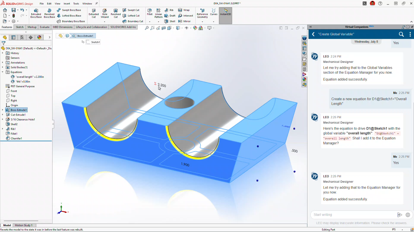
          Equation Assistant

          Writing equations inside SOLIDWORKS has never been difficult, but remembering the correct syntax certainly can be.

          Equation Assistant allows engineers to describe the relationship they want.

          LEO creates the equation, validates the syntax and even helps troubleshoot errors before they’re applied.

          Equation Assistant

          Expert SOLIDWORKS Guidance

          Perhaps one of the most underrated additions is Expert Guidance.

          Instead of searching the Help documentation or the internet, LEO provides modelling recommendations based on SOLIDWORKS best practices directly inside your workflow.

          For newer users, it’s almost like having a CSWA-level mentor available whenever you need one.

          Expert SOLIDWORKS Guidance

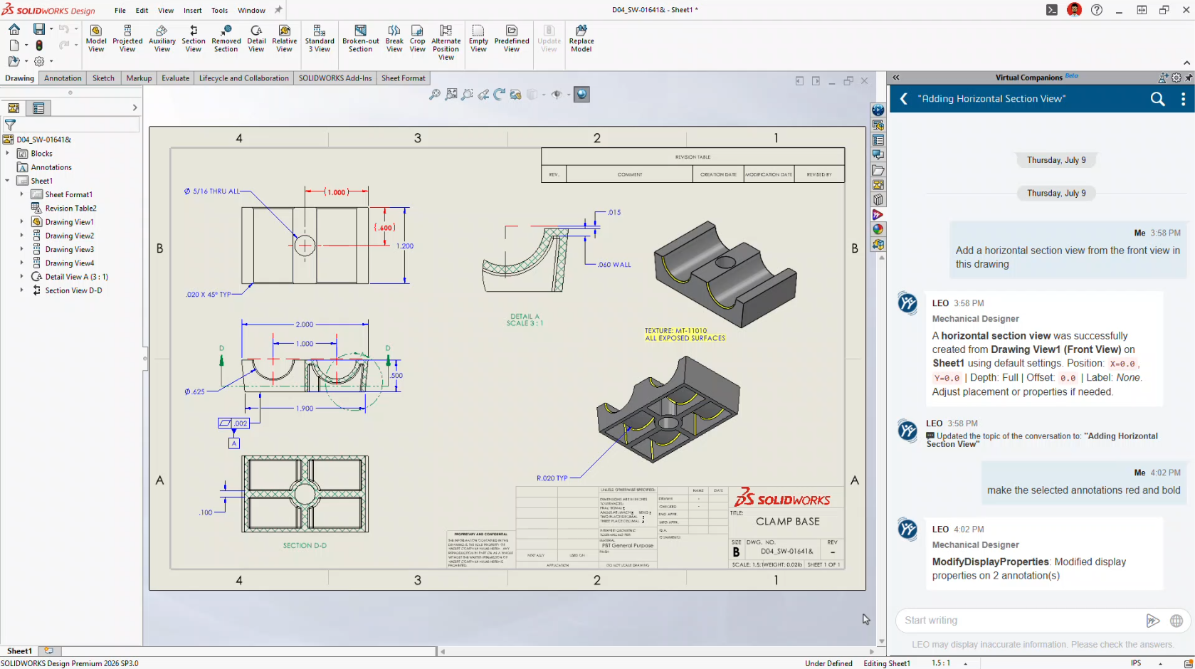
          AI Makes Drawing Creation Even Easier

          Drawing automation continues to improve significantly.

          FD02 introduced Auto-Generate Drawings.

          FD03 transforms it into a conversational workflow.

          Instead of navigating dozens of PropertyManagers, you simply tell LEO what you want.

          LEO can now:

          • Create drawing views

          • Change view scales

          • Position views

          • Rotate views

          • Adjust line weights

          • Insert annotations

          • Generate flat patterns

          • Create bend tables

          • Export DXF

          • Export PDF

          The goal isn’t to replace engineering review.

          It’s to eliminate the repetitive setup work that consumes so much time.

          AI Makes Drawing Creation Even Easier

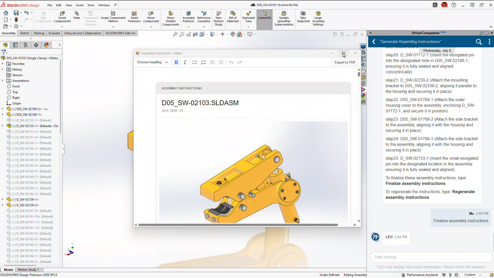
          Automatic Assembly Instructions

          Another brand-new capability is Assembly Instruction Generation.

          Using your existing CAD data, LEO can automatically generate step-by-step assembly instructions complete with visual snapshots.

          Potential applications include:

          • Manufacturing work instructions

          • Service documentation

          • Training manuals

          • Assembly guides

          Documentation has traditionally been one of the least enjoyable parts of engineering.

          This feature could dramatically reduce that workload.

          Automatic Assembly Instructions

          Smarter Large Assembly Management

          FD03 also builds on the Assembly Performance improvements introduced in FD02.

          Instead of simply identifying performance issues, LEO can now actively recommend solutions.

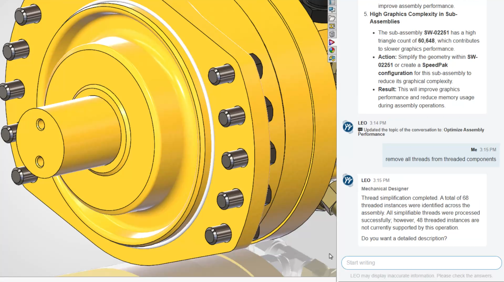
          Thread Simplification

          Modeled threads consume significant system resources.

          LEO can identify imported fasteners with modeled threads and convert them into cosmetic threads while preserving drawing representation.

          The result is smaller files and noticeably faster assembly performance.

          Thread Simplification

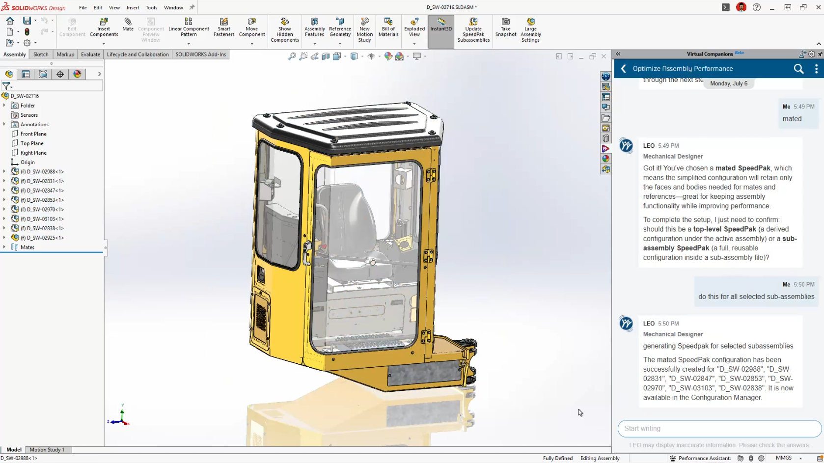
          AI-Guided SpeedPak Creation

          SpeedPak has always been one of SOLIDWORKS’ most powerful large assembly tools.

          Many users simply aren’t sure when, or how, to use it effectively.

          LEO now recommends appropriate SpeedPak strategies based on your assembly structure and automatically generates them for you.

          For companies working with large assemblies every day, this could become one of the most valuable additions in FD03.

          AI-Guided SpeedPak Creation

          PLM Information Without Leaving SOLIDWORKS

          For customers using Cloud Services or the 3DEXPERIENCE platform, LEO continues to bridge the gap between CAD and PLM.

          Rather than navigating multiple dashboards, you can simply ask questions like:

          • Who owns this file?

          • What revision is it?

          • Are there pending approvals?

          • What configurations exist?

          • Are there open change actions?

          It’s another example of AI reducing navigation while making information easier to access.

          What FD03 Means for SOLIDWORKS Users

          If FD02 introduced AI-powered tools, FD03 introduces an AI-powered workflow.

          LEO is gradually becoming the central interface for interacting with SOLIDWORKS, allowing engineers to work more naturally using conversation instead of commands.

          More importantly, SOLIDWORKS continues to take a practical approach to AI.

          None of these features attempt to replace engineers.

          Instead, they focus on reducing repetitive work, improving productivity, and helping users get more value from SOLIDWORKS without changing the way they already design.

          That’s exactly where AI delivers the greatest benefit.

          Ready to Explore SOLIDWORKS AI?

          Many of the features introduced in FD03 are available as part of the latest SOLIDWORKS Design Functional Delivery, with additional capabilities continuing to roll out throughout the year.

          At Solidxperts, we’re continuously testing the latest AI enhancements so we can help our customers understand not just what’s new, but how to apply these tools to real engineering projects.

          Whether you’re looking to modernize your design workflow, improve productivity, or simply explore what AI can do inside SOLIDWORKS, our team is here to help.


          Michael Habrich

          3DEXPERIENCE Specialist

          X_green_halo

          Any questions? Need help? Ask one of our experts.

          Whether you’re ready to get started or just have a few more questions, you can contact us toll-free:
            From CAD to Wax: How MJP 3D Printing Is Transforming Jewelry Manufacturing

            BLOG

            From CAD to Wax: How MJP 3D Printing Is Transforming Jewelry Manufacturing

            [techtips_featured_image_shortcode]

            A new piece of jewelry can begin with just a few lines in a CAD software. But before it becomes a piece made of gold, silver, or another precious metal, that design still has to go through an essential step: becoming a physical model precise enough to be integrated into the casting process.

            And this is where things get interesting.

            What happens when a design is particularly complex? When a customer requests a customization? When several variations of the same model need to be produced? Or when a model needs to be manufactured quickly without creating new tooling?

            Additive manufacturing offers a direct answer: produce the wax model directly from the digital file.

            This is precisely the application for which 3D Systems’ MultiJet Printing (MJP) solutions have been developed. By combining a printer designed for jewelry models, dedicated wax materials, and 3D Sprint preparation software, the workflow can move directly from digital design to a model intended for the lost-wax casting process.

            When Every Detail Matters

            In jewelry manufacturing, a few fractions of a millimeter can make a significant difference.

            A model may contain fine details, sharp edges, organic shapes, or complex geometries. For the final result to remain faithful to the original design, the wax model must reproduce these characteristics accurately.

            The ProJet MJP 2500W Plus was specifically developed to produce wax casting patterns for jewelry applications. It uses VisiJet 100% wax materials designed to produce models faithful to the CAD design, with sharp edges and precise detail definition. 3D Systems also indicates that certain materials are designed to melt like traditional casting waxes and burn out without ash residue.

            The MJP 300W Plus offers several print modes designed to meet different production requirements. Its Premium ZHD mode uses an 8 μm layer thickness, while the QHD and XHD modes use 14.1 μm and 16 μm layer thicknesses, respectively. The system’s stated typical dimensional accuracy is ±0.0508 mm per 25.4 mm of part dimension.

            The MJP 300W Plus also offers a QHD mode with a stated resolution of 2,400 × 1,800 × 1,800 dpi. These different print modes make it possible to adapt the process to the desired balance between detail, surface quality, and productivity.

            The goal is therefore not simply to produce a model that resembles the original design. It is to reproduce the characteristics of the digital model as accurately as possible before integrating it into the casting process.

            Why Print Directly in Wax?

            The answer lies in the workflow.

            When a model is produced using traditional methods, several intermediate steps may be required. Depending on the application, creating a master model and a mold may also be part of the process.

            3D wax printing offers a different approach: the digital file becomes the direct starting point for manufacturing the physical model.

            CAD model → digital preparation → wax printing → lost-wax casting → final metal part

            This approach makes it possible to produce a physical model directly from the digital design. A modification made to the CAD file can then be prepared for a new print without necessarily having to recreate a master model or mold for every variation.

            This can be particularly interesting for customized jewelry, small production runs, and designs requiring multiple iterations.

            Additive manufacturing does not replace every traditional jewelry manufacturing method. Instead, it offers another way to produce certain models when customization, geometric complexity, or process flexibility are priorities.

            3D Sprint: Connecting Design and Manufacturing

            A precision 3D printer can only produce data that has been properly prepared for manufacturing.

            This is why software plays an essential role in the workflow.

            3D Sprint is 3D Systems’ additive manufacturing preparation and production management software. It is used to prepare digital data and organize models for compatible systems.

            In jewelry applications, the preparation capabilities go beyond simply positioning models on a build platform. On the MJP 300W Plus, sprues and runners can be accessed through the Strut function, facilitating the addition of structures required to prepare certain parts for casting. The software also includes the Surface Enhance function, designed to improve certain surfaces depending on the needs of the model.

            The result is a more cohesive workflow:

            CAD design → preparation in 3D Sprint → MJP printing → wax model → casting

            Digital preparation therefore becomes an integral part of the manufacturing process. The final result depends not only on the printer, but also on how the model is prepared for production.

            One Printer, Multiple Ways to Produce

            Not every jewelry model requires the same balance between resolution, speed, and productivity.

            This is why the MJP 300W Plus offers multiple print modes.

            The XHD mode is designed to balance speed and quality for the production of larger batches.

            The Premium ZHD mode, with an 8 μm layer thickness, is designed to produce highly detailed models, particularly for upward-facing surfaces.

            The QHD mode offers a resolution of 2,400 × 1,800 × 1,800 dpi according to 3D Systems’ specifications.

            This flexibility makes it possible to adapt the process to the model being produced. A highly detailed part may require a different priority than a production run consisting of a large number of models.

            The best configuration is therefore not necessarily the one that maximizes resolution alone. The appropriate mode should be selected based on the required level of detail, geometry, and production volume.

            A Workflow That Evolves with the Design

            Jewelry is an industry where customization plays an important role.

            A model may need to be modified to meet a customer’s requirements. A collection may require several sizes or variations. A new design may need to be tested before being introduced into larger-scale production.

            In these situations, digital manufacturing offers significant flexibility.

            The design can be modified in the CAD file. The new file can then be prepared and printed.

            The ability to move quickly between the physical model and the digital model reduces the distance between design and production.

            The development process becomes more flexible: a design can be tested, modified, and reproduced as the project evolves.

            A Real-World Example: The Narsakka Case Study

            One of the best ways to understand the value of a workflow is to look at what happens in a real production environment.

            Narsakka, a Finnish jewelry company, integrated a 3D Systems wax 3D printing solution to produce models intended for casting.

            According to the case study published by 3D Systems, Narsakka can produce 60 to 100 wax models in just four hours, helping reduce production lead times from several weeks to a few days.

            The company uses the ProJet MJP 2500W with VisiJet M2 CAST material. The workflow also uses soluble and fusible support materials, allowing batch support removal and quick access to models ready for casting.

            The case study also highlights another advantage of a digital workflow: flexibility. Narsakka uses the solution for both larger production batches and more specialized custom jewelry production.

            According to 3D Systems, the company also eliminated the need for master models and rubber molds in its process and reported a 100% success rate for the parts produced as part of the case study. These results should naturally be understood within the specific context of Narsakka’s application and production process, but they clearly illustrate the potential of an integrated digital workflow.

            Why Choose an MJP Solution Over Another Technology?

            Not all 3D printing technologies are designed to meet the same requirements.

            For the production of jewelry models, several factors must be considered simultaneously:

            • accuracy;

            • the ability to reproduce fine details;

            • surface quality;

            • the material being used;

            • compatibility with the casting process;

            • production speed;

            • the amount of post-processing required.

            This is where 3D Systems’ approach becomes particularly interesting. The solution is not limited to a printer.

            It combines an MJP technology designed for jewelry models, wax materials compatible with the casting process, and a software environment that enables files to be prepared for manufacturing.

            For a jewelry manufacturer, this means evaluating the solution as a complete workflow rather than comparing only the resolution or speed of a machine.

            From Digital Design to the Final Piece

            Additive manufacturing does not change the creativity at the heart of jewelry making.

            It changes how certain designs can be transformed into physical models.

            A complex model can be prepared digitally. A customization can be integrated into the CAD file. Multiple variations can be produced. A wax model can then be integrated into the casting process.

            For jewelry professionals in Montreal and across Quebec, MJP 3D printing offers a way to further integrate digital manufacturing into an existing workflow.

            The question is not simply whether a 3D printer can produce a wax model.

            The real question is:

            What could you produce if your digital design could become a precise, repeatable casting pattern directly integrated into your production process?

            With its MJP solutions, VisiJet wax materials, and 3D Sprint software, 3D Systems offers an integrated approach to bringing digital design closer to jewelry manufacturing.

            From CAD to wax. From wax to metal. And from a digital idea to a real piece.


            Lilian

            Lilian Beatrix

            Additive Manufacturing Specialist

            X_green_halo

            Any questions? Need help? Ask one of our experts.

            Whether you’re ready to get started or just have a few more questions, you can contact us toll-free:
              SOLIDWORKS AI: Auto-generate SOLIDWORKS Macros

              BLOG

              SOLIDWORKS AI: Auto-generate SOLIDWORKS Macros

              [techtips_featured_image_shortcode]

              Editor’s Note (Updated): This article captures our initial observations after discovering the AI Macro Generation interface in an early SOLIDWORKS 2026 release. Since then, the feature has been officially introduced in SOLIDWORKS 2026 FD03. We’ve left this article online for historical context, but we recommend reading our updated guide for the most current information and feature walkthrough.

              Is SOLIDWORKS About to Generate Macros for You?

              If you’ve been exploring the latest updates in SOLIDWORKS 2026 SP2.1 and 3DEXPERIENCE FD02, you might have noticed something… unexpected.

              Buried under Tools > Macro, there’s a new option:
              “Auto-generate”, complete with the AURA logo.

              At first glance, it doesn’t do much (yet). But it raises an interesting question:

              👉 Is SOLIDWORKS getting ready to generate macros for you using AI?

              Let’s take a closer look at what’s going on, and what it could mean for your day-to-day work.

              What We Found in the Interface

              Here’s where things get interesting.

              Inside the Macro menu, alongside familiar options like Record and Edit, there’s now:

              • Auto-generate

              • Marked with the AURA icon

              At the same time, digging into the AI Labs tab reveals something even more telling:

              Macro Generation listed as a competency

              That’s not placeholder language. That’s a capability label.

              So… What Is AURA, Exactly?

              If you’ve followed recent updates on the 3DEXPERIENCE platform, you’ve probably heard of AURA.

              AURA is Dassault Systèmes’ push into context-aware AI assistance, not just generating content, but actually:

              • Understanding what you’re doing

              • Anticipating next steps

              • Helping automate repetitive tasks

              In other words, it’s not just “AI for show.” It’s meant to sit inside your workflow.

              Macro generation fits that direction perfectly.

              Why This Matters (More Than It Looks)

              Let’s be honest, macros in SOLIDWORKS are powerful, but:

              • Most users don’t write them

              • Many rely on recorded macros (which are fragile)

              • Editing VBA code isn’t exactly user-friendly

              Now imagine this instead:

              👉 You describe what you want:

              “Rename all selected components using this convention”

              👉 And SOLIDWORKS builds the macro for you.

              That’s the gap this feature is aiming to close.

              What AI Macro Generation Could Look Like

              While the feature isn’t active yet, we can make some realistic assumptions based on current AI direction:

              1. Prompt-Based Automation

              You type a request, similar to how you interact with AI tools today.

              2. Context Awareness

              Instead of generic scripts, it understands:

              • Assembly structure

              • Selected components

              • Active document type

              3. Editable Output

              It likely generates:

              • VBA macros (initially)

              • Possibly with explanations or annotations

              4. Iterative Refinement

              Not quite right? Adjust the prompt instead of rewriting code.

              Is This Feature Live Yet?

              Short answer: No, not fully.

              Right now:

              • The Auto-generate option appears in the UI

              • But doesn’t execute (at least in SP2.1 environments we’ve tested)

              This strongly suggests:

              • It’s either feature-gated

              • Or not yet connected to backend AI services

              So no, you’re not missing a setting, it’s just not ready.

              Not an Easter Egg, A Direction

              It’s tempting to think this was accidentally left in the UI.

              But given:

              • The AURA branding

              • The AI Labs “Macro Generation” competency

              • The broader AI rollout in FD02

              This looks intentional.

              👉 More likely: a preview of what’s coming next

              What This Means for SOLIDWORKS Users

              If (or when) this becomes active, it could shift how teams approach automation:

              Less Dependency on API Expertise

              You won’t need to:

              • Learn VBA

              • Dig through API documentation

              Faster Process Standardization

              Teams could quickly:

              • Build repeatable workflows

              • Enforce naming conventions

              • Automate tedious cleanup tasks

              Lower Barrier to Entry

              More users can leverage automation, not just power-users.

              A Practical Example

              Let’s say your team regularly:

              • Imports vendor models

              • Needs to clean up feature trees

              • Apply materials

              • Rename files

              Today:

              • That’s either manual

              • Or handled by a fragile macro

              With AI macro generation:

              You could describe the workflow once, and reuse it reliably.

              Where This Fits in the Bigger Picture

              This isn’t happening in isolation.

              Dassault Systèmes is clearly moving toward:

              • AI-assisted modeling

              • Context-aware recommendations

              • Automation without coding

              Macro generation is just one piece of that puzzle.

              Should You Be Excited?

              Cautiously yes.

              But with realistic expectations:

              • First versions will likely be limited

              • Output may need validation

              • Complex workflows might still require manual refinement

              Still, even a 50% time savings on repetitive tasks is meaningful.

              Final Thoughts

              Right now, the Auto-generate macro button is more promise than product.

              But it tells us something important:

              👉 SOLIDWORKS isn’t just adding AI features, it’s rethinking how users interact with automation.

              And if this lands the way it’s intended, it could make one of the most underused features in SOLIDWORKS… actually usable.

              Want to Stay Ahead of What’s Coming?

              At Solidxperts, we keep a close eye on updates like this—not just what’s announced, but what’s emerging.

              If you want help:

              • Identifying automation opportunities

              • Preparing your team for AI-assisted workflows

              • Or getting more out of your SOLIDWORKS environment

              Reach out at info@solidxperience.com, we’re always happy to talk shop.


              Michael Habrich

              3DEXPERIENCE Specialist

              X_green_halo

              Any questions? Need help? Ask one of our experts.

              Whether you’re ready to get started or just have a few more questions, you can contact us toll-free:
                SOLIDWORKS vs. Inventor: Which CAD Software Is Better for Mechanical Design?

                BLOG

                SOLIDWORKS vs. Inventor: Which CAD Software Is Better for Mechanical Design?

                [techtips_featured_image_shortcode]

                Meet the Contenders

                SOLIDWORKS is Dassault Systèmes’ desktop CAD platform, purpose-built for mechanical product design from day one. It covers everything from concept sketching through detailed part and assembly modeling, simulation, rendering, and production-ready drawings. Its ecosystem (PDM, Simulation, CAM, Visualize) is tightly integrated, and its user community is one of the largest in the engineering world. SOLIDWORKS excels in consumer products, complex surfacing, weldments, sheet metal, and any project where design intent needs to be communicated clearly across teams.

                By comparison, Autodesk Inventor is a professional-grade 3D mechanical design tool built around parametric modeling, simulation, and tooling design. It lives inside the broader Autodesk ecosystem (AutoCAD, Vault, Fusion 360) and has traditionally been strong in large-assembly industrial equipment, structural frame design, and manufacturing workflows that lean heavily on AutoCAD-derived 2D documentation. If your shop grew up on AutoCAD, Inventor feels like a natural next step into 3D.

                Where each shines at a glance:

                When it comes to large structural frames and weldments, both platforms are competent and will get the job done.

                However, the similarities start to diverge from there. Inventor’s standout advantage is its deep interoperability with AutoCAD. SOLIDWORKS, on the other hand, pulls ahead in nearly every other category that matters to a mechanical designer. It offers significantly stronger tools for consumer product design and complex surfacing, where Inventor’s capabilities feel limited by comparison. In addition, sheet metal workflows are more mature and production-ready in SOLIDWORKS, and its desktop simulation tools go deeper without needing to leave the modeling environment. Finally, the SOLIDWORKS community and library of learning resources dwarfs what’s available on the Inventor side,  a real advantage when you’re troubleshooting an unfamiliar workflow or trying to push the software into new territory.

                Mechanical Design: Strengths & Weaknesses

                Why You Might Choose SOLIDWORKS

                Strengths:

                • Intuitive Sketch & Feature Workflow: SOLIDWORKS was designed from the ground up around a sketch-then-feature paradigm that just makes sense for mechanical parts. The FeatureManager tree is logical, sketch relations are visual and predictable, and the software rarely fights you when you need to go back and edit an early feature. Design intent stays intact, changes are easily made and automatic updating of not just parts but also assemblies really show the full power of parametric design.

                • Simulation Integration (SOLIDWORKS Simulation): Running FEA, thermal, fatigue, or flow studies without leaving the modeling environment is a massive time-saver. You don’t export, re-mesh, and re-apply loads in a separate tool. You right-click your assembly, set up a study, and iterate. For mechanical designers who need to validate before prototyping, this tight loop is invaluable.

                • Sheet Metal & Weldments: SOLIDWORKS’ sheet metal tools handle complex bends, forming tools, lofted bends, and flat-pattern exports with a maturity that Inventor still chases. Weldment profiles, cut lists, and trim/extend operations are clean and production-ready. If your shop cuts, bends, and welds steel daily, SOLIDWORKS speaks your language fluently.

                Weaknesses:

                • Large Assembly Performance: SOLIDWORKS can struggle with very large assemblies (10,000+ components) unless you’re disciplined about using Lightweight mode, SpeedPak configurations, and large design review mode. Inventor historically handles brute-force large assemblies with slightly less pain out of the box, though the gap has narrowed.

                • Data Management Cost & Complexity: SOLIDWORKS PDM Professional is powerful but adds significant licensing cost and IT overhead (SQL Server, dedicated vault server, client deployments). For smaller shops, the jump from file-folder chaos to a properly managed PDM environment is steep, both financially and administratively.

                • Subscription Pricing Pressure: Dassault’s push toward subscription and the 3DEXPERIENCE platform has created uncertainty for long-time perpetual-license users. The cost trajectory is upward, and some features are being nudged toward cloud-connected workflows that not every mechanical design shop is ready for.

                Why You Might Choose Autodesk Inventor

                Strengths:

                • Frame Generator & Bolted Connections: Inventor’s Frame Generator is genuinely excellent. You pick a structural profile from a library, sketch a skeleton, and the tool builds the frame with automatic mitre cuts, end treatments, and a BOM that’s ready for fabrication. For anyone designing conveyor systems, machine guards, or structural steel, this workflow is fast and reliable.

                • AutoCAD & Vault Integration: If your company has decades of AutoCAD legacy data, Inventor reads and references DWG files natively. Vault (Autodesk’s data management tool) ties Inventor models and AutoCAD drawings together without format translation headaches. That continuity matters when you’re maintaining equipment that was first drawn in AutoCAD R14.

                • iLogic Rules-Based Design: Inventor’s iLogic lets you embed design rules directly into parts and assemblies without needing a full API. For configurable products (think: custom conveyor lengths, bracket sizes, or enclosure variants), iLogic can drive dimensions, suppress features, and swap components based on simple if/then logic. It lowers the barrier to automation compared to writing full macros.

                Weaknesses:

                • Surfacing Tools Are Limited: When a mechanical design crosses into organic shapes, blends, or consumer-product aesthetics, Inventor’s surfacing toolkit feels thin. You’ll hit walls trying to create complex curvature-continuous surfaces that SOLIDWORKS handles with relative ease.

                • Drawing Environment Feels Dated: Despite improvements over the years, Inventor’s drawing environment still carries quirks inherited from AutoCAD thinking. Balloon management, BOM customization, and view annotation can feel clunky compared to the more streamlined SOLIDWORKS drawing workflow, especially on assemblies with hundreds of components.

                • Smaller Ecosystem & Community: Finding a quick answer to an obscure Inventor problem takes longer. The forums are active but smaller, third-party add-ins are fewer, and training content (especially advanced topics) is less abundant. When you’re stuck at 4 PM on a Friday with a deadline, community size matters.

                Why SOLIDWORKS Wins for Mechanical Design

                After years on both platforms, I made the switch to SOLIDWORKS a decade ago and never looked back.

                Here’s the honest reason: SOLIDWORKS thinks like a mechanical designer. Every tool, menu, and workflow feels like it was built by someone who has actually sat at a drafting board trying to communicate a design to a machinist or a fabricator.

                Inventor is capable, genuinely capable, but it often feels like a 3D layer bolted onto an AutoCAD philosophy, that is slowly being left behind as autodesk focuses more on Fusion 360. It offers features that designers may not be geared to designers like 3d studio meant for animation studios, factory design utilities are specific to manufacturing engineers not designers and BIM capabilities meant for a very specific user group. SOLIDWORKS was born 3D-native, and that DNA shows in every interaction with meaningful tools for designers like, toolbox, design checker, tolerance analyst, interference checking, collision detection, surface flattening, and pipe, tube and electrical routing.

                Beyond the general feel, two features specifically set SOLIDWORKS apart:

                Feature 1: Design Intent Through Configurations

                SOLIDWORKS’ Configuration system is remarkably powerful for mechanical design. A single part file can represent an entire family of components, different lengths, bore sizes, material thicknesses, all driven by a design table or manual configuration switches. This isn’t just convenience; it’s how real mechanical products work. A bracket comes in five sizes. A shaft has three keyway options. Configurations let you model that reality once and maintain it in one place. Inventor’s iPart/iAssembly approach is similar in concept but clunkier in execution, especially when configurations interact with drawings, BOMs, and PDM.

                Feature 2: The Drawing-to-Model Associativity

                SOLIDWORKS drawings are not just views of a model. They are live, bidirectional windows into it. You can dimension a feature in the drawing and drive the model from there. Annotations, tolerances, and GD&T travel with the model as MBD (Model-Based Definition) data. For a mechanical designer whose deliverable is ultimately a production drawing or a 3D-annotated model sent to a CNC shop, this associativity means fewer errors, faster ECOs, and less time reconciling what the drawing says versus what the model actually is.

                The Bottom Line

                Both tools will get parts designed and drawings out the door. But if your world is mechanical product design, parts, assemblies, drawings, simulation, and manufacturing communication, SOLIDWORKS offers a tighter, more intuitive experience. Fewer interface sections offer a more user friendly experience, with sheet metal and weldments all being able to be done in the part environment. Inventor has around 6 different environments with different specific uses. Solidworks tries to evolve the way mechanical designers actually think making it one of the most widely used CAD programs in a variety of different markets and disciplines.

                Ready to see whether SOLIDWORKS is the right fit for your mechanical design workflow? Contact the Solidxperts team to discuss your needs and explore the best solution for your business.


                Edward Ricciardi

                Solutions Specialist

                X_green_halo

                Any questions? Need help? Ask one of our experts.

                Whether you’re ready to get started or just have a few more questions, you can contact us toll-free:
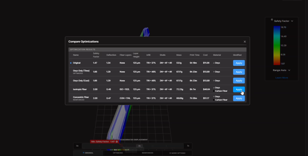
                  Uninstalling 3DEXPERIENCE SOLIDWORKS and the SOLIDWORKS Connector

                  BLOG

                  Uninstalling 3DEXPERIENCE SOLIDWORKS and the SOLIDWORKS Connector

                  [techtips_featured_image_shortcode]

                  Both 3DEXPERIENCE SOLIDWORKS (SOLIDWORKS Connected) and the Design with SOLIDWORKS connector can be removed directly from the 3DEXPERIENCE platform. If platform access is no longer available, they can also be uninstalled through Windows.

                  Below are the recommended methods, starting with the simplest approach.

                  Option 1: Uninstall from the 3DEXPERIENCE Platform

                  This is the preferred method when you still have access to your 3DEXPERIENCE tenant.

                  1. Log in to the 3DEXPERIENCE platform.

                  2. Click the Compass (image) icon in the upper-left corner.

                  3. Under My Roles, select:

                    • 3DEXPERIENCE SOLIDWORKS (for SOLIDWORKS Connected), or

                    • Collaborative Designer for SOLIDWORKS (for the Design with SOLIDWORKS connector)

                  Steps for uninstalling 3DEXPERIENCE SOLIDWORKS components

                  4. Locate the SOLIDWORKS app under the selected role.

                  5. Click the down arrow next to the app and select Uninstall.

                  ### **Alt text (EN)** Steps to uninstall 3DEXPERIENCE SOLIDWORKS components on Windows

                  You’ll be prompted to confirm the uninstall twice. Confirm both messages to proceed.

                  User interface showing SOLIDWORKS Connector uninstallation processInterface showing the progress of uninstalling the SOLIDWORKS Connector in 3DEXPERIENCE SOLIDWORKS on Windows

                  Once complete, a confirmation message will appear at the bottom of the apps window indicating the uninstall was successful.

                  Uninstall Progress Window for SOLIDWORKS Connector in 3DEXPERIENCE

                  Option 2: Uninstall from the Windows Control Panel

                  If access to the 3DEXPERIENCE platform has been discontinued, you can uninstall using Windows.

                  1. Open the Windows Control Panel

                    • The quickest way is to click Start and search for Control Panel

                  2. Select Uninstall a program

                    • If using icon view, go to Programs and Features

                  Window showing the progress of removing the SOLIDWORKS Connector in 3DEXPERIENCE SOLIDWORKS on Windows

                  3. Locate one of the following:

                    • Dassault Systèmes R20XXx SOLIDWORKS (for SOLIDWORKS Connected)

                    • Dassault Systèmes xCAD Connectors (for the SOLIDWORKS Connector)

                  4. Select the application and click Uninstall/ChangeUser interface displaying the ongoing uninstallation of the SOLIDWORKS Connector within 3DEXPERIENCE SOLIDWORKS

                  5. Confirm the uninstall when prompted

                  A progress dialog will appear. Once it closes, the uninstall is complete.

                  Performing a Clean Uninstall (Advanced)

                  In rare cases typically when reinstalling or resolving persistent issues a clean uninstall may be required.

                  Important: This process involves removing system components and editing the Windows registry. We strongly recommend working with your IT team or Solidxperts Technical Support before proceeding.

                  Step 1: Remove Prerequisites

                  After uninstalling SOLIDWORKS Connected or the SOLIDWORKS Connector, return to Control Panel → Uninstall a program and remove only the following items.

                  ⚠️ Do not uninstall other Microsoft Visual C++ versions, as they may be required by other applications.

                  • 3DEXPERIENCE Launcher

                  • CEF for SOLIDWORKS Applications

                  • Dassault Systèmes Software VC10 Prerequisites x86-x64

                  • Dassault Systèmes Software VC11 Prerequisites x86-x64

                  • Microsoft Visual C++ 2012 Redistributable (x86 & x64)

                  • Microsoft Visual C++ 2013 Redistributable (x86 & x64)

                  • Microsoft Visual C++ 2015–2019 Redistributable (x86 & x64)

                  • Microsoft Visual Studio Tools for Applications 2019

                  • WPTx64

                  • Visual Basic (VBA) 7.1

                  Step 2: Delete Remaining Folders

                  Some folders may be hidden. In File Explorer, enable View → Show → Hidden items.

                  Delete the following folders if they exist:

                  C:\Program Files\Dassault Systemes\SOLIDWORKS 3DEXPERIENCE
                  C:\Program Files\Dassault Systemes\B4XXxcadconnectors
                  C:\Program Files\Common Files\SOLIDWORKS Shared
                  C:\Program Files (x86)\Common Files\SOLIDWORKS Shared
                  C:\Users\Public\Documents\SOLIDWORKS
                  C:\Users\Public\Documents\Dassault Systemes
                  C:\ProgramData\DassaultSystemes\3DEXPERIENCELauncher
                  C:\ProgramData\SOLIDWORKS
                  C:\Users\<UserName>\AppData\Roaming\DassaultSystemes
                  C:\Users\<UserName>\AppData\Roaming\SOLIDWORKS
                  C:\Users\<UserName>\AppData\Local\TempSWBackupDirectory
                  C:\Users\<UserName>\AppData\Local\DassaultSystemes
                  C:\Users\<UserName>\AppData\Local\SolidWorks

                  Step 3: Clean the Registry (Advanced)

                  ⚠️ Caution: Incorrect registry changes can cause serious system issues. Always consult an IT professional before proceeding.

                  Remove the following registry keys if present:

                  HKEY_CURRENT_USER\Software\Dassault Systemes\SolidWorks Shared
                  HKEY_CURRENT_USER\Software\Dassault Systemes\SolidWorksPDM
                  HKEY_CURRENT_USER\Software\SolidWorks
                  HKEY_LOCAL_MACHINE\SOFTWARE\Dassault Systemes\SolidWorksPDM
                  HKEY_LOCAL_MACHINE\SOFTWARE\Dassault Systemes\SwxConnectors
                  HKEY_LOCAL_MACHINE\SOFTWARE\Dassault Systemes\V6_Common
                  HKEY_LOCAL_MACHINE\SOFTWARE\SolidWorks
                  HKEY_LOCAL_MACHINE\SOFTWARE\Srac
                  HKEY_LOCAL_MACHINE\SOFTWARE\WOW6432Node\SolidWorks

                  Step 4 and Final Step: Restart

                  Once all steps are complete, restart the computer to finalize the cleanup.

                  Final Thoughts

                  In most cases, uninstalling directly from the 3DEXPERIENCE platform or Windows Control Panel is all that’s required. A clean uninstall should only be used when troubleshooting or preparing for a fresh installation.

                  If you have questions or run into issues, your Solidxperts Technical Support team is here to help just reach out.

                  Looking to go further?

                  • Check out more tips and tutorials on our YouTube channel.

                  • Explore best practices with our experts.

                  • Or reach out to our team, we’re here to help you get the most out of your platform.

                  Your platform should work the way your team works and we’re here to help make that happen.


                  Michael Habrich

                  3DEXPERIENCE Specialist

                  X_green_halo

                  Any questions? Need help? Ask one of our experts.

                  Whether you’re ready to get started or just have a few more questions, you can contact us toll-free:

                    How Additive Manufacturing with Markforged Helped Avoid the Costly Replacement of a Cooler

                    BLOG

                    How Additive Manufacturing with Markforged Helped Avoid the Costly Replacement of a Cooler

                    [techtips_featured_image_shortcode]

                    Can you already smell the BBQ?

                    Last summer, I went to a store to buy a cooler. I found one at an unbeatable price, but it was missing two retaining pins for the handle.

                    That’s when I had an idea.

                    Why not design and 3D print them?

                    So, I left the store with the cooler, a big smile on my face, and full confidence that I could find a solution in time for the BBQ.

                    BBQ Solidxperts
                    BBQ Solidxperts x Markforged

                    Challenge: A Cooler with Missing Parts

                    A BBQ was scheduled just a few days later. I wanted to buy a cooler to keep drinks cold throughout the evening, but my budget was limited.

                    I came across a brand-new 45.4 L cooler for the modest price of $15 CAD. The only issue was that it was missing the two pins that secured the handle on one side. Despite searching throughout the store, I was unable to find replacement parts that could be purchased with it.

                    Without these pins, the cooler was still usable, but moving it around would have been much less convenient since the handle would not function properly. A comparable new cooler would have cost approximately $50 CAD before taxes. Ordering replacement parts was also an option, but not necessarily the most cost-effective one due to potential shipping costs and delivery delays.

                    With a BBQ quickly approaching, I needed a solution that was both effective and fast.

                    Evaluating the Options

                    Let’s take a quick look at the available options:

                    • Purchase a New Cooler : The simplest solution, but also the most expensive unless a significant discount is available.

                    • Order the Missing Parts : A viable option, but the total cost could quickly increase due to part pricing, shipping fees, and delivery times.

                    • Manufacture the Parts In-House : An ideal solution for a company that has access to a 3D printer and the expertise needed to quickly design replacement parts.

                    Considering the tight timeline, the very low production cost, and the minimal effort required to design and print the parts, I chose additive manufacturing.

                    Markforged printers can produce durable parts using materials such as onyx, nylon, carbon fiber, fiberglass, and even metal. This makes them an excellent solution for challenges like this one.

                    Designing and Printing the Pins

                    I brought the cooler to my colleague, Charles-Olivier Provost, and in less than two hours, the problem was solved.

                    The process was straightforward. He removed one of the existing pins from the functional side of the handle and measured its dimensions using calipers, including diameter, length, and other key features. Using those measurements, he recreated the part in SOLIDWORKS. The modeling process took only a few minutes.

                    Once the model was completed, it was exported to Markforged’s Eiger software to prepare it for printing.

                    Pièce dans Eiger
                    The modeled part imported into Markforged Eiger.

                    A few minutes later, the print job was launched on a Markforged X7 printer using an onyx material. In just over an hour, the two replacement parts were ready.

                    Impression Markforged
                    Launching the print job on the Markforged X7 3D printer.

                    Results

                    Once the two parts were printed, they were installed in their respective locations. A few quick tests confirmed that the handle functioned perfectly, just as if the cooler were brand new.

                    That was when my colleague told me, “Your cooler is ready.”

                    The moment I had been waiting for.

                    For me, it was the satisfaction of having made a great purchase while staying within budget and meeting the BBQ deadline. For Charles-Olivier, it was the satisfaction of solving a practical problem using precise measurements, SOLIDWORKS, and his secret weapon: a Markforged 3D printer.

                    The savings were significant. The pair of replacement parts cost approximately $1.50 CAD to produce, compared to the potential cost of ordering replacement parts with shipping fees or purchasing a brand-new cooler.

                    Pièce finale
                    Cooler repaired using a 3D-printed replacement pin (black part).

                    How 3D Printing Reduces Costs and Lead Times

                    In an industrial setting, the parts involved can represent equipment worth thousands or even tens of thousands of dollars.

                    3D printing stands out because of its flexibility and rapid production capabilities. When the availability of a replacement part becomes a challenge and a solution is needed quickly, additive manufacturing truly demonstrates its value.

                    Extending the lifespan of products not only helps reduce costs but also contributes to more sustainable and responsible practices.

                    To learn more about additive manufacturing and the Markforged solutions offered by SolidXperts, visit: 3D Printing and Scanning Solutions – Solidxperts


                    Chung Ping Lu, eng.

                    Chung Ping Lu, eng.

                    Senior Technical Representative

                    X_green_halo

                    Any questions? Need help? Ask one of our experts.

                    Whether you’re ready to get started or just have a few more questions, you can contact us toll-free:

                        Download

                          Download

                            Download