SOLIDWORKS AI: Auto-generate SOLIDWORKS Macros

BLOG

SOLIDWORKS AI: Auto-generate SOLIDWORKS Macros

[techtips_featured_image_shortcode]

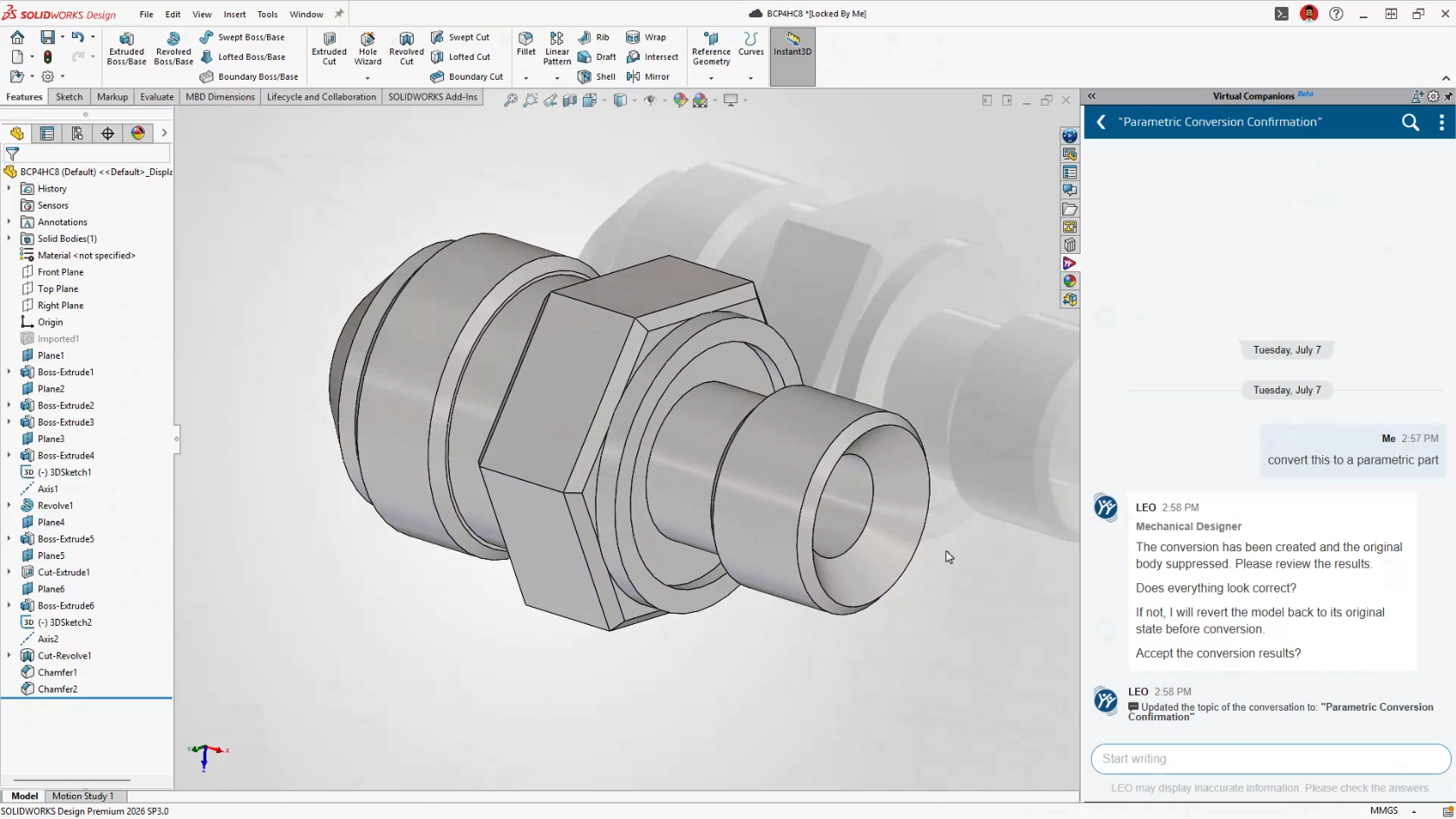
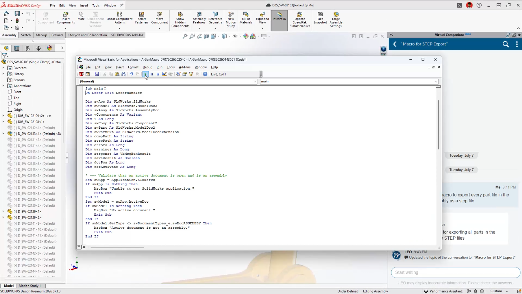
Editor’s Note (Updated): This article captures our initial observations after discovering the AI Macro Generation interface in an early SOLIDWORKS 2026 release. Since then, the feature has been officially introduced in SOLIDWORKS 2026 FD03. We’ve left this article online for historical context, but we recommend reading our updated guide for the most current information and feature walkthrough.

Is SOLIDWORKS About to Generate Macros for You?

If you’ve been exploring the latest updates in SOLIDWORKS 2026 SP2.1 and 3DEXPERIENCE FD02, you might have noticed something… unexpected.

Buried under Tools > Macro, there’s a new option:
“Auto-generate”, complete with the AURA logo.

At first glance, it doesn’t do much (yet). But it raises an interesting question:

👉 Is SOLIDWORKS getting ready to generate macros for you using AI?

Let’s take a closer look at what’s going on, and what it could mean for your day-to-day work.

What We Found in the Interface

Here’s where things get interesting.

Inside the Macro menu, alongside familiar options like Record and Edit, there’s now:

  • Auto-generate

  • Marked with the AURA icon

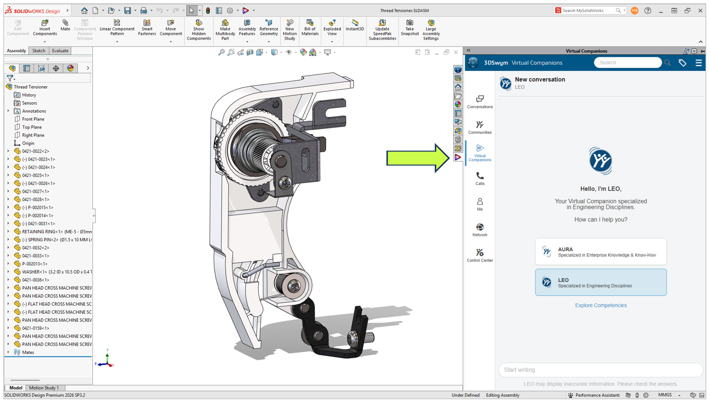
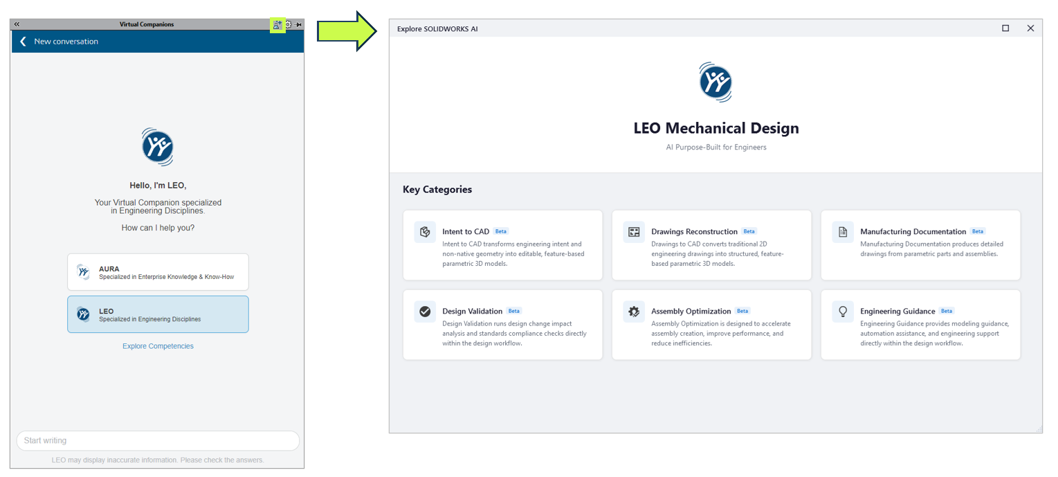
At the same time, digging into the AI Labs tab reveals something even more telling:

Macro Generation listed as a competency

That’s not placeholder language. That’s a capability label.

So… What Is AURA, Exactly?

If you’ve followed recent updates on the 3DEXPERIENCE platform, you’ve probably heard of AURA.

AURA is Dassault Systèmes’ push into context-aware AI assistance, not just generating content, but actually:

  • Understanding what you’re doing

  • Anticipating next steps

  • Helping automate repetitive tasks

In other words, it’s not just “AI for show.” It’s meant to sit inside your workflow.

Macro generation fits that direction perfectly.

Why This Matters (More Than It Looks)

Let’s be honest, macros in SOLIDWORKS are powerful, but:

  • Most users don’t write them

  • Many rely on recorded macros (which are fragile)

  • Editing VBA code isn’t exactly user-friendly

Now imagine this instead:

👉 You describe what you want:

“Rename all selected components using this convention”

👉 And SOLIDWORKS builds the macro for you.

That’s the gap this feature is aiming to close.

What AI Macro Generation Could Look Like

While the feature isn’t active yet, we can make some realistic assumptions based on current AI direction:

1. Prompt-Based Automation

You type a request, similar to how you interact with AI tools today.

2. Context Awareness

Instead of generic scripts, it understands:

  • Assembly structure

  • Selected components

  • Active document type

3. Editable Output

It likely generates:

  • VBA macros (initially)

  • Possibly with explanations or annotations

4. Iterative Refinement

Not quite right? Adjust the prompt instead of rewriting code.

Is This Feature Live Yet?

Short answer: No, not fully.

Right now:

  • The Auto-generate option appears in the UI

  • But doesn’t execute (at least in SP2.1 environments we’ve tested)

This strongly suggests:

  • It’s either feature-gated

  • Or not yet connected to backend AI services

So no, you’re not missing a setting, it’s just not ready.

Not an Easter Egg, A Direction

It’s tempting to think this was accidentally left in the UI.

But given:

  • The AURA branding

  • The AI Labs “Macro Generation” competency

  • The broader AI rollout in FD02

This looks intentional.

👉 More likely: a preview of what’s coming next

What This Means for SOLIDWORKS Users

If (or when) this becomes active, it could shift how teams approach automation:

Less Dependency on API Expertise

You won’t need to:

  • Learn VBA

  • Dig through API documentation

Faster Process Standardization

Teams could quickly:

  • Build repeatable workflows

  • Enforce naming conventions

  • Automate tedious cleanup tasks

Lower Barrier to Entry

More users can leverage automation, not just power-users.

A Practical Example

Let’s say your team regularly:

  • Imports vendor models

  • Needs to clean up feature trees

  • Apply materials

  • Rename files

Today:

  • That’s either manual

  • Or handled by a fragile macro

With AI macro generation:

You could describe the workflow once, and reuse it reliably.

Where This Fits in the Bigger Picture

This isn’t happening in isolation.

Dassault Systèmes is clearly moving toward:

  • AI-assisted modeling

  • Context-aware recommendations

  • Automation without coding

Macro generation is just one piece of that puzzle.

Should You Be Excited?

Cautiously yes.

But with realistic expectations:

  • First versions will likely be limited

  • Output may need validation

  • Complex workflows might still require manual refinement

Still, even a 50% time savings on repetitive tasks is meaningful.

Final Thoughts

Right now, the Auto-generate macro button is more promise than product.

But it tells us something important:

👉 SOLIDWORKS isn’t just adding AI features, it’s rethinking how users interact with automation.

And if this lands the way it’s intended, it could make one of the most underused features in SOLIDWORKS… actually usable.

Want to Stay Ahead of What’s Coming?

At Solidxperts, we keep a close eye on updates like this—not just what’s announced, but what’s emerging.

If you want help:

  • Identifying automation opportunities

  • Preparing your team for AI-assisted workflows

  • Or getting more out of your SOLIDWORKS environment

Reach out at info@solidxperience.com, we’re always happy to talk shop.


Michael Habrich

3DEXPERIENCE Specialist

X_green_halo

Any questions? Need help? Ask one of our experts.

Whether you’re ready to get started or just have a few more questions, you can contact us toll-free:

    SOLIDWORKS vs. Inventor: Which CAD Software Is Better for Mechanical Design?

    BLOG

    SOLIDWORKS vs. Inventor: Which CAD Software Is Better for Mechanical Design?

    [techtips_featured_image_shortcode]

    Meet the Contenders

    SOLIDWORKS is Dassault Systèmes’ desktop CAD platform, purpose-built for mechanical product design from day one. It covers everything from concept sketching through detailed part and assembly modeling, simulation, rendering, and production-ready drawings. Its ecosystem (PDM, Simulation, CAM, Visualize) is tightly integrated, and its user community is one of the largest in the engineering world. SOLIDWORKS excels in consumer products, complex surfacing, weldments, sheet metal, and any project where design intent needs to be communicated clearly across teams.

    By comparison, Autodesk Inventor is a professional-grade 3D mechanical design tool built around parametric modeling, simulation, and tooling design. It lives inside the broader Autodesk ecosystem (AutoCAD, Vault, Fusion 360) and has traditionally been strong in large-assembly industrial equipment, structural frame design, and manufacturing workflows that lean heavily on AutoCAD-derived 2D documentation. If your shop grew up on AutoCAD, Inventor feels like a natural next step into 3D.

    Where each shines at a glance:

    When it comes to large structural frames and weldments, both platforms are competent and will get the job done.

    However, the similarities start to diverge from there. Inventor’s standout advantage is its deep interoperability with AutoCAD. SOLIDWORKS, on the other hand, pulls ahead in nearly every other category that matters to a mechanical designer. It offers significantly stronger tools for consumer product design and complex surfacing, where Inventor’s capabilities feel limited by comparison. In addition, sheet metal workflows are more mature and production-ready in SOLIDWORKS, and its desktop simulation tools go deeper without needing to leave the modeling environment. Finally, the SOLIDWORKS community and library of learning resources dwarfs what’s available on the Inventor side,  a real advantage when you’re troubleshooting an unfamiliar workflow or trying to push the software into new territory.

    Mechanical Design: Strengths & Weaknesses

    Why You Might Choose SOLIDWORKS

    Strengths:

    • Intuitive Sketch & Feature Workflow: SOLIDWORKS was designed from the ground up around a sketch-then-feature paradigm that just makes sense for mechanical parts. The FeatureManager tree is logical, sketch relations are visual and predictable, and the software rarely fights you when you need to go back and edit an early feature. Design intent stays intact, changes are easily made and automatic updating of not just parts but also assemblies really show the full power of parametric design.

    • Simulation Integration (SOLIDWORKS Simulation): Running FEA, thermal, fatigue, or flow studies without leaving the modeling environment is a massive time-saver. You don’t export, re-mesh, and re-apply loads in a separate tool. You right-click your assembly, set up a study, and iterate. For mechanical designers who need to validate before prototyping, this tight loop is invaluable.

    • Sheet Metal & Weldments: SOLIDWORKS’ sheet metal tools handle complex bends, forming tools, lofted bends, and flat-pattern exports with a maturity that Inventor still chases. Weldment profiles, cut lists, and trim/extend operations are clean and production-ready. If your shop cuts, bends, and welds steel daily, SOLIDWORKS speaks your language fluently.

    Weaknesses:

    • Large Assembly Performance: SOLIDWORKS can struggle with very large assemblies (10,000+ components) unless you’re disciplined about using Lightweight mode, SpeedPak configurations, and large design review mode. Inventor historically handles brute-force large assemblies with slightly less pain out of the box, though the gap has narrowed.

    • Data Management Cost & Complexity: SOLIDWORKS PDM Professional is powerful but adds significant licensing cost and IT overhead (SQL Server, dedicated vault server, client deployments). For smaller shops, the jump from file-folder chaos to a properly managed PDM environment is steep, both financially and administratively.

    • Subscription Pricing Pressure: Dassault’s push toward subscription and the 3DEXPERIENCE platform has created uncertainty for long-time perpetual-license users. The cost trajectory is upward, and some features are being nudged toward cloud-connected workflows that not every mechanical design shop is ready for.

    Why You Might Choose Autodesk Inventor

    Strengths:

    • Frame Generator & Bolted Connections: Inventor’s Frame Generator is genuinely excellent. You pick a structural profile from a library, sketch a skeleton, and the tool builds the frame with automatic mitre cuts, end treatments, and a BOM that’s ready for fabrication. For anyone designing conveyor systems, machine guards, or structural steel, this workflow is fast and reliable.

    • AutoCAD & Vault Integration: If your company has decades of AutoCAD legacy data, Inventor reads and references DWG files natively. Vault (Autodesk’s data management tool) ties Inventor models and AutoCAD drawings together without format translation headaches. That continuity matters when you’re maintaining equipment that was first drawn in AutoCAD R14.

    • iLogic Rules-Based Design: Inventor’s iLogic lets you embed design rules directly into parts and assemblies without needing a full API. For configurable products (think: custom conveyor lengths, bracket sizes, or enclosure variants), iLogic can drive dimensions, suppress features, and swap components based on simple if/then logic. It lowers the barrier to automation compared to writing full macros.

    Weaknesses:

    • Surfacing Tools Are Limited: When a mechanical design crosses into organic shapes, blends, or consumer-product aesthetics, Inventor’s surfacing toolkit feels thin. You’ll hit walls trying to create complex curvature-continuous surfaces that SOLIDWORKS handles with relative ease.

    • Drawing Environment Feels Dated: Despite improvements over the years, Inventor’s drawing environment still carries quirks inherited from AutoCAD thinking. Balloon management, BOM customization, and view annotation can feel clunky compared to the more streamlined SOLIDWORKS drawing workflow, especially on assemblies with hundreds of components.

    • Smaller Ecosystem & Community: Finding a quick answer to an obscure Inventor problem takes longer. The forums are active but smaller, third-party add-ins are fewer, and training content (especially advanced topics) is less abundant. When you’re stuck at 4 PM on a Friday with a deadline, community size matters.

    Why SOLIDWORKS Wins for Mechanical Design

    After years on both platforms, I made the switch to SOLIDWORKS a decade ago and never looked back.

    Here’s the honest reason: SOLIDWORKS thinks like a mechanical designer. Every tool, menu, and workflow feels like it was built by someone who has actually sat at a drafting board trying to communicate a design to a machinist or a fabricator.

    Inventor is capable, genuinely capable, but it often feels like a 3D layer bolted onto an AutoCAD philosophy, that is slowly being left behind as autodesk focuses more on Fusion 360. It offers features that designers may not be geared to designers like 3d studio meant for animation studios, factory design utilities are specific to manufacturing engineers not designers and BIM capabilities meant for a very specific user group. SOLIDWORKS was born 3D-native, and that DNA shows in every interaction with meaningful tools for designers like, toolbox, design checker, tolerance analyst, interference checking, collision detection, surface flattening, and pipe, tube and electrical routing.

    Beyond the general feel, two features specifically set SOLIDWORKS apart:

    Feature 1: Design Intent Through Configurations

    SOLIDWORKS’ Configuration system is remarkably powerful for mechanical design. A single part file can represent an entire family of components, different lengths, bore sizes, material thicknesses, all driven by a design table or manual configuration switches. This isn’t just convenience; it’s how real mechanical products work. A bracket comes in five sizes. A shaft has three keyway options. Configurations let you model that reality once and maintain it in one place. Inventor’s iPart/iAssembly approach is similar in concept but clunkier in execution, especially when configurations interact with drawings, BOMs, and PDM.

    Feature 2: The Drawing-to-Model Associativity

    SOLIDWORKS drawings are not just views of a model. They are live, bidirectional windows into it. You can dimension a feature in the drawing and drive the model from there. Annotations, tolerances, and GD&T travel with the model as MBD (Model-Based Definition) data. For a mechanical designer whose deliverable is ultimately a production drawing or a 3D-annotated model sent to a CNC shop, this associativity means fewer errors, faster ECOs, and less time reconciling what the drawing says versus what the model actually is.

    The Bottom Line

    Both tools will get parts designed and drawings out the door. But if your world is mechanical product design, parts, assemblies, drawings, simulation, and manufacturing communication, SOLIDWORKS offers a tighter, more intuitive experience. Fewer interface sections offer a more user friendly experience, with sheet metal and weldments all being able to be done in the part environment. Inventor has around 6 different environments with different specific uses. Solidworks tries to evolve the way mechanical designers actually think making it one of the most widely used CAD programs in a variety of different markets and disciplines.

    Ready to see whether SOLIDWORKS is the right fit for your mechanical design workflow? Contact the Solidxperts team to discuss your needs and explore the best solution for your business.


    Edward Ricciardi

    Solutions Specialist

    X_green_halo

    Any questions? Need help? Ask one of our experts.

    Whether you’re ready to get started or just have a few more questions, you can contact us toll-free:

      Uninstalling 3DEXPERIENCE SOLIDWORKS and the SOLIDWORKS Connector

      BLOG

      Uninstalling 3DEXPERIENCE SOLIDWORKS and the SOLIDWORKS Connector

      [techtips_featured_image_shortcode]

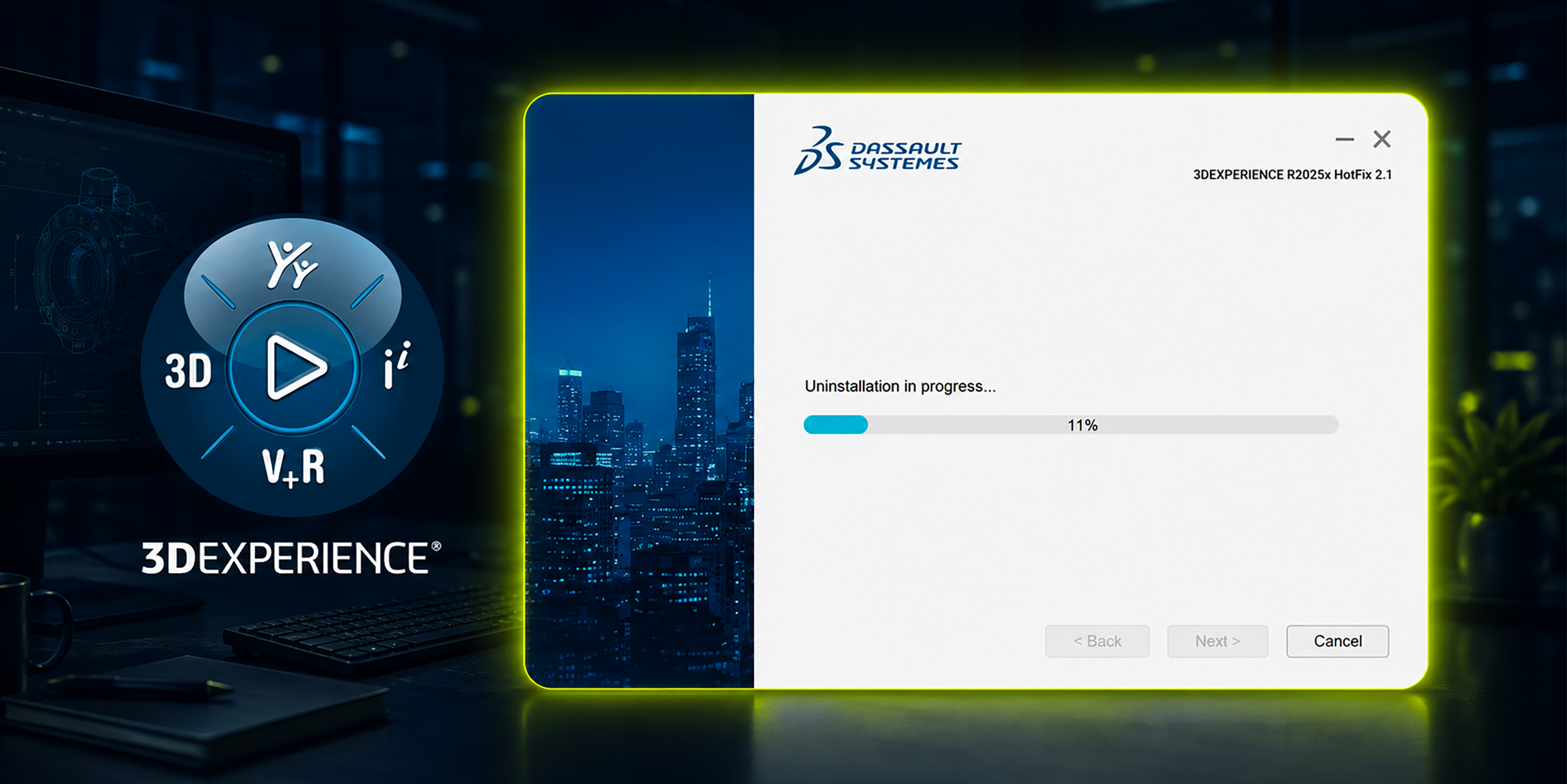
      Both 3DEXPERIENCE SOLIDWORKS (SOLIDWORKS Connected) and the Design with SOLIDWORKS connector can be removed directly from the 3DEXPERIENCE platform. If platform access is no longer available, they can also be uninstalled through Windows.

      Below are the recommended methods, starting with the simplest approach.

      Option 1: Uninstall from the 3DEXPERIENCE Platform

      This is the preferred method when you still have access to your 3DEXPERIENCE tenant.

      1. Log in to the 3DEXPERIENCE platform.

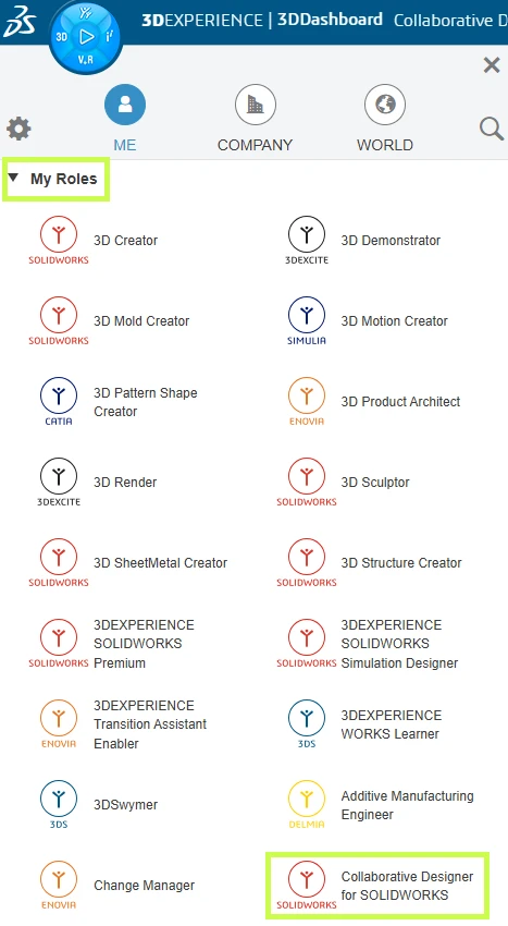
      2. Click the Compass (image) icon in the upper-left corner.

      3. Under My Roles, select:

        • 3DEXPERIENCE SOLIDWORKS (for SOLIDWORKS Connected), or

        • Collaborative Designer for SOLIDWORKS (for the Design with SOLIDWORKS connector)

      Steps for uninstalling 3DEXPERIENCE SOLIDWORKS components

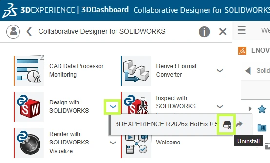
      4. Locate the SOLIDWORKS app under the selected role.

      5. Click the down arrow next to the app and select Uninstall.

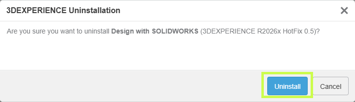
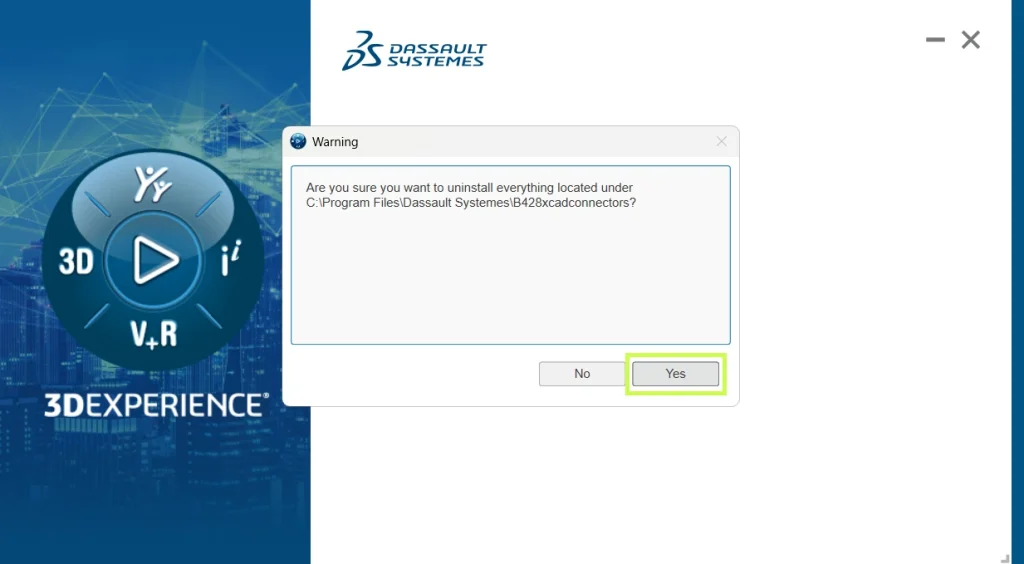
      ### **Alt text (EN)** Steps to uninstall 3DEXPERIENCE SOLIDWORKS components on Windows

      You’ll be prompted to confirm the uninstall twice. Confirm both messages to proceed.

      User interface showing SOLIDWORKS Connector uninstallation processInterface showing the progress of uninstalling the SOLIDWORKS Connector in 3DEXPERIENCE SOLIDWORKS on Windows

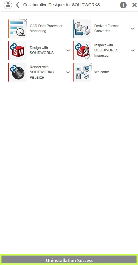
      Once complete, a confirmation message will appear at the bottom of the apps window indicating the uninstall was successful.

      Uninstall Progress Window for SOLIDWORKS Connector in 3DEXPERIENCE

      Option 2: Uninstall from the Windows Control Panel

      If access to the 3DEXPERIENCE platform has been discontinued, you can uninstall using Windows.

      1. Open the Windows Control Panel

        • The quickest way is to click Start and search for Control Panel

      2. Select Uninstall a program

        • If using icon view, go to Programs and Features

      Window showing the progress of removing the SOLIDWORKS Connector in 3DEXPERIENCE SOLIDWORKS on Windows

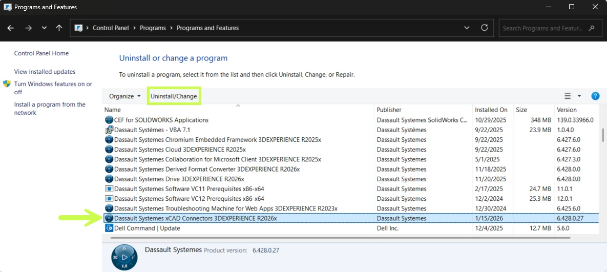
      3. Locate one of the following:

        • Dassault Systèmes R20XXx SOLIDWORKS (for SOLIDWORKS Connected)

        • Dassault Systèmes xCAD Connectors (for the SOLIDWORKS Connector)

      4. Select the application and click Uninstall/ChangeUser interface displaying the ongoing uninstallation of the SOLIDWORKS Connector within 3DEXPERIENCE SOLIDWORKS

      5. Confirm the uninstall when prompted

      A progress dialog will appear. Once it closes, the uninstall is complete.

      Performing a Clean Uninstall (Advanced)

      In rare cases typically when reinstalling or resolving persistent issues a clean uninstall may be required.

      Important: This process involves removing system components and editing the Windows registry. We strongly recommend working with your IT team or Solidxperts Technical Support before proceeding.

      Step 1: Remove Prerequisites

      After uninstalling SOLIDWORKS Connected or the SOLIDWORKS Connector, return to Control Panel → Uninstall a program and remove only the following items.

      ⚠️ Do not uninstall other Microsoft Visual C++ versions, as they may be required by other applications.

      • 3DEXPERIENCE Launcher

      • CEF for SOLIDWORKS Applications

      • Dassault Systèmes Software VC10 Prerequisites x86-x64

      • Dassault Systèmes Software VC11 Prerequisites x86-x64

      • Microsoft Visual C++ 2012 Redistributable (x86 & x64)

      • Microsoft Visual C++ 2013 Redistributable (x86 & x64)

      • Microsoft Visual C++ 2015–2019 Redistributable (x86 & x64)

      • Microsoft Visual Studio Tools for Applications 2019

      • WPTx64

      • Visual Basic (VBA) 7.1

      Step 2: Delete Remaining Folders

      Some folders may be hidden. In File Explorer, enable View → Show → Hidden items.

      Delete the following folders if they exist:

      C:\Program Files\Dassault Systemes\SOLIDWORKS 3DEXPERIENCE
      C:\Program Files\Dassault Systemes\B4XXxcadconnectors
      C:\Program Files\Common Files\SOLIDWORKS Shared
      C:\Program Files (x86)\Common Files\SOLIDWORKS Shared
      C:\Users\Public\Documents\SOLIDWORKS
      C:\Users\Public\Documents\Dassault Systemes
      C:\ProgramData\DassaultSystemes\3DEXPERIENCELauncher
      C:\ProgramData\SOLIDWORKS
      C:\Users\<UserName>\AppData\Roaming\DassaultSystemes
      C:\Users\<UserName>\AppData\Roaming\SOLIDWORKS
      C:\Users\<UserName>\AppData\Local\TempSWBackupDirectory
      C:\Users\<UserName>\AppData\Local\DassaultSystemes
      C:\Users\<UserName>\AppData\Local\SolidWorks

      Step 3: Clean the Registry (Advanced)

      ⚠️ Caution: Incorrect registry changes can cause serious system issues. Always consult an IT professional before proceeding.

      Remove the following registry keys if present:

      HKEY_CURRENT_USER\Software\Dassault Systemes\SolidWorks Shared
      HKEY_CURRENT_USER\Software\Dassault Systemes\SolidWorksPDM
      HKEY_CURRENT_USER\Software\SolidWorks
      HKEY_LOCAL_MACHINE\SOFTWARE\Dassault Systemes\SolidWorksPDM
      HKEY_LOCAL_MACHINE\SOFTWARE\Dassault Systemes\SwxConnectors
      HKEY_LOCAL_MACHINE\SOFTWARE\Dassault Systemes\V6_Common
      HKEY_LOCAL_MACHINE\SOFTWARE\SolidWorks
      HKEY_LOCAL_MACHINE\SOFTWARE\Srac
      HKEY_LOCAL_MACHINE\SOFTWARE\WOW6432Node\SolidWorks

      Step 4 and Final Step: Restart

      Once all steps are complete, restart the computer to finalize the cleanup.

      Final Thoughts

      In most cases, uninstalling directly from the 3DEXPERIENCE platform or Windows Control Panel is all that’s required. A clean uninstall should only be used when troubleshooting or preparing for a fresh installation.

      If you have questions or run into issues, your Solidxperts Technical Support team is here to help just reach out.

      Looking to go further?

      • Check out more tips and tutorials on our YouTube channel.

      • Explore best practices with our experts.

      • Or reach out to our team, we’re here to help you get the most out of your platform.

      Your platform should work the way your team works and we’re here to help make that happen.


      Michael Habrich

      3DEXPERIENCE Specialist

      X_green_halo

      Any questions? Need help? Ask one of our experts.

      Whether you’re ready to get started or just have a few more questions, you can contact us toll-free:
        Top Graphics Cards for SOLIDWORKS

        BLOG

        Top Graphics Cards for SOLIDWORKS

        [techtips_featured_image_shortcode]

        You’ve spent hours perfecting a complex car engine assembly, but the moment you try to rotate the view, the screen stutters and freezes. This dreaded assembly lag isn’t a reflection of your design skills. It’s a cry for help from your hardware.

        While the main computer chip handles the underlying logic of your design, your Graphics Processing Unit (GPU) acts as the computer’s “Visual Engine.” According to workstation builders, the GPU takes on the massive math required to physically display your work on screen. Equipping a proper CAD graphics card ensures that visual math happens instantly.

        Pushing this visual heavy-lifting over to a dedicated card is known as hardware acceleration. Without it, your machine struggles to hold all the geometry in its short-term memory, resulting in choppy movements that make 3D modeling feel like drawing on a moving target.

        Most users assume any expensive gaming component will fix this problem, but industry data reveals a completely different story. Securing the best graphics card for SOLIDWORKS actually requires specialized, certified software drivers that create a stable handshake with the program, delivering the fluid performance you desperately need.

        Gaming Cards vs. Workstation GPUs: Why Price Does Not Equal Performance

        At first glance, dropping a fortune on a top-tier gaming PC might seem like the smartest move for running SOLIDWORKS. However, an expensive gaming graphics card often causes more crashes and visual glitches than a standard $500 professional workstation card. The reason behind this is because a gaming card focuses on refresh speed, instead of calculating large amount of complex graphic data. Meaning that being able to go at 200km/h will not be useful when you need to lift 2000KG of data, without dropping it.

        The reason is simple: the secret behind this difference is a Certified Driver. Think of a driver as a specialized handshake between SOLIDWORKS and your hardware. Professional manufacturers work directly with SOLIDWORKS to certify compatibility, ensuring both systems speak the exact same language without stuttering. This deep software testing explains why using specialized workstation drivers for SOLIDWORKS stability makes much more sense than relying on consumer gear tuned for fast video games.

        Comparing gaming versus professional graphics cards for 3D design reveals that consumer hardware completely lacks the specific tools SOLIDWORKS needs to display complex parts accurately. As a result, sticking to a professional GPU gives you exclusive access to crucial workflow protections:

        • Certified Drivers: Guaranteed software harmony to prevent sudden crashes during a complex design session.

        • RealView Graphics: A built-in feature that instantly renders realistic lighting and material textures on your model while you work.

        • OIT (Order Independent Transparency): The processing power required to smoothly look through overlapping clear parts, like a glass windshield over a dashboard, without the screen glitching or tearing.

        Investing in a certified family of cards, such as NVIDIA RTX or AMD Radeon Pro for CAD, guarantees you aren’t fighting your hardware. Once you have a stable professional card picked out, you simply need to ensure it has enough room to hold your models. That brings us to VRAM: the “workbench” of your 3D designs.

        VRAM: The ‘Workbench’ of Your 3D Designs

        Think of Video RAM (VRAM) as your physical workbench. A small desk works perfectly for designing a simple bicycle gear, but assembling an entire drone requires much more table space before parts start falling off the edges. Rotating a basic 3D model uses VRAM to hold that structural geometry in front of you. However, adding realistic lighting or reflections drastically changes the impact of VRAM on CAD rendering speed, because generating high-resolution textures requires a noticeably larger workspace than standard wireframe modeling.

        Unfortunately, running out of this workspace creates a frustrating bottleneck. If your design exceeds your VRAM capacity, the computer is forced to constantly swap parts in and out of slower, long-term storage. You will notice this struggle immediately when applying surface finishes, resulting in stuttering screens or flickering textures that fail to load. Even the best workstation laptop graphics cards will suffer these exact visual glitches if they lack the necessary memory capacity for your specific workload.

        Sizing your memory properly comes down to evaluating your typical project scale. Most everyday designers will work very smoothly with 4GB to 8GB of VRAM. Conversely, the graphics card memory requirements for complex simulations or massive assemblies safely push you toward 32GB or more. Selecting the right hardware family depends entirely on this baseline memory requirement. Note that more than 64GB of VRAM is rarely needed.

        Now that your “workbench” is sized correctly, you must choose who builds it. The professional market is dominated by NVIDIA and AMD, but your first stop shouldn’t be a spec sheet it should be the Dassault Systèmes SOLIDWORKS Certified hardware list. This list is a guarantee that the manufacturer and SOLIDWORKS have tested the card specifically to prevent unexpected crashes. Buying a certified card is the safest way to ensure your hardware investment actually works when you open a complex file.

        When comparing these two giants, you will quickly encounter the term CUDA cores. Think of these as individual workers inside the NVIDIA graphics chip; the more workers you have, the faster they can calculate and render a realistic image of your product. While AMD’s Radeon Pro cards offer excellent value and their own efficient computing units, NVIDIA’s RTX series currently holds the edge in the broader CAD industry because of how efficiently these CUDA workers handle heavy 3D math.

        Finding the price-to-performance sweet spot means matching your daily tasks to the right hardware tier without overspending. To simplify the decision, here is a breakdown to help you find the best graphics card for SOLIDWORKS based on your typical projects:

        • Best budget GPU for SOLIDWORKS students: NVIDIA RTX A1000 (Perfect for learning and small assemblies).

        • Small Office Sweet Spot: AMD Radeon Pro W6600 or NVIDIA RTX A2000 (Ideal for smooth, medium-sized daily engineering).

        • Industrial Designer Peak: NVIDIA RTX 5000 Ada (Necessary when handling massive, complete machines).

        Even if you are tempted to look at extreme top-tier data like NVIDIA RTX 6000 Ada versus RTX A6000 benchmarks, remember that most everyday users will never need that massive level of power. A mid-range certified card will keep your design process perfectly stable and fluid.

        From Lag to Liquid: Optimizing Settings for Your New Hardware

        Your brand-new professional card won’t work its magic automatically straight out of the box. To actually see the realistic lighting and reflections you just paid for, you need to know how to enable RealView Graphics in SOLIDWORKS. Look at the top of your workspace screen for the “Heads-up View Toolbar” and click the small sphere icon. Toggling this feature transforms your flat, dull part into a realistic material like shiny steel or textured plastic, proving your hardware investment was worth it.

        Beyond the visual upgrades, you must force Windows to use your hardware efficiently by optimizing SOLIDWORKS performance settings. Search your computer for “Graphics Settings” and look for a toggle called “Hardware-accelerated GPU scheduling.” Think of this setting as hiring a dedicated traffic cop for your system’s visual data. Turning it on tells your computer to hand off the heavy 3D math directly to your new graphics card, keeping your complex assemblies rotating smoothly without bogging down your processor.

        Occasionally, even the best systems might display strange jagged lines or missing model faces. When troubleshooting SOLIDWORKS graphical glitches and artifacts, your first step is usually just updating your certified driver rather than calling expensive IT support. These “artifacts” are simply short-term communication hiccups between the design software and your hardware. Keeping your drivers properly updated ensures these hiccups are resolved quickly, keeping your workflow completely seamless.

        Your SOLIDWORKS Hardware Roadmap: Making the Final Decision

        At this point, you no longer have to guess why your screen stutters while rotating parts. By understanding how your computer’s visual engine handles heavy lifting, you’ve moved from the frustration of assembly lag to the promise of fluid design. You now know that investing in proper SOLIDWORKS hardware isn’t about chasing expensive gaming specs it’s about selecting the right professional tool.

        While tech forums can easily drag you into the trap of “it depends,” an entry-level professional card typically offers the perfect balance. These professional workstation GPUs for large assembly modeling ensure that crucial specialized handshake happens between your software and hardware. This agreement guarantees the certified drivers necessary to secure a stable, crash-free design environment.

        Before making a final purchase, run your chosen card through this simple three-step verification checklist:

        • Verify the Handshake: Is the exact card model listed on the official SOLIDWORKS hardware certification page?

        • Check the Workbench: Does it have at least 8GB of VRAM to comfortably hold your models and future-proof your setup?

        • Match the Workflow: If you plan to render photorealistic images, is this a recommended GPU for SOLIDWORKS Visualize?

        Imagine opening a massive, complex assembly and effortlessly spinning it on your screen with realistic textures applied, completely confident in your hardware investment. That level of smooth, crash-free creativity is now entirely within your reach. Start by checking your current computer’s VRAM today, and use that baseline to take your first confident step toward a better workstation.

        Want to Learn More?

        Discover more tips and tutorials on our YouTube channel.

        Explore best practices with our experts.

        Or contact our team, we’re here to help you get the most out of your platform.


        Dominic Martel

        Solutions Specialist

        X_green_halo

        Any questions? Need help? Ask one of our experts.

        Whether you’re ready to get started or just have a few more questions, you can contact us toll-free:
          Which Raise3D Solution Is Right for Your Industrial 3D Printing Needs?

          BLOG

          Which Raise3D Solution Is Right for Your Industrial 3D Printing Needs?

          [techtips_featured_image_shortcode]

          Over the past few years, 3D printing has evolved far beyond rapid prototyping. Today, it is widely used across industrial environments for tooling, functional parts, product development, supply chain optimization, and even end-use production.

          However, as the technology has matured, however, one reality has become increasingly clear: there is no single 3D printing solution that fits every application.

          From FDM and resin printing to polymer powder technologies, each platform offers different advantages in terms of precision, mechanical performance, production volume, and operating costs.

          As a result, Raise3D has established itself as a compelling option for organizations seeking a balance between performance, accessibility, and versatility.

          At Solidxperts, we help organizations evaluate, implement, and optimize these solutions as part of a broader additive manufacturing strategy. Raise3D is not a universal answer to every challenge; however, it often fits a wide range of industrial applications very well.

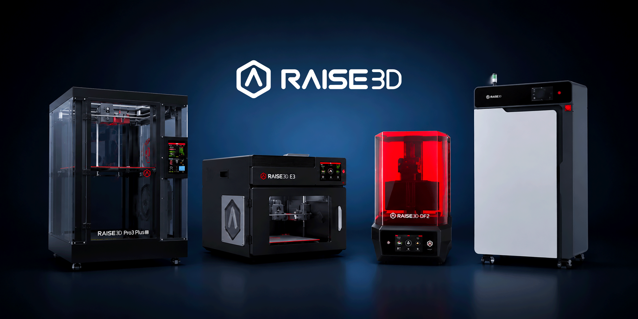
          Raise3D Pro3 and Pro3 Plus: A Versatile Starting Point

          For many organizations, adopting 3D printing begins with a straightforward objective: producing functional parts in-house without relying on external suppliers.

          This is exactly where the Pro3 series excels.

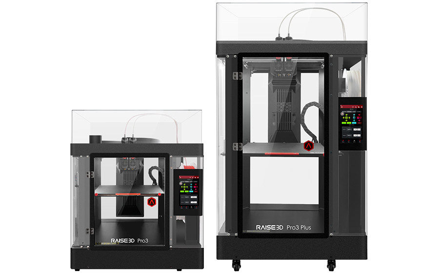
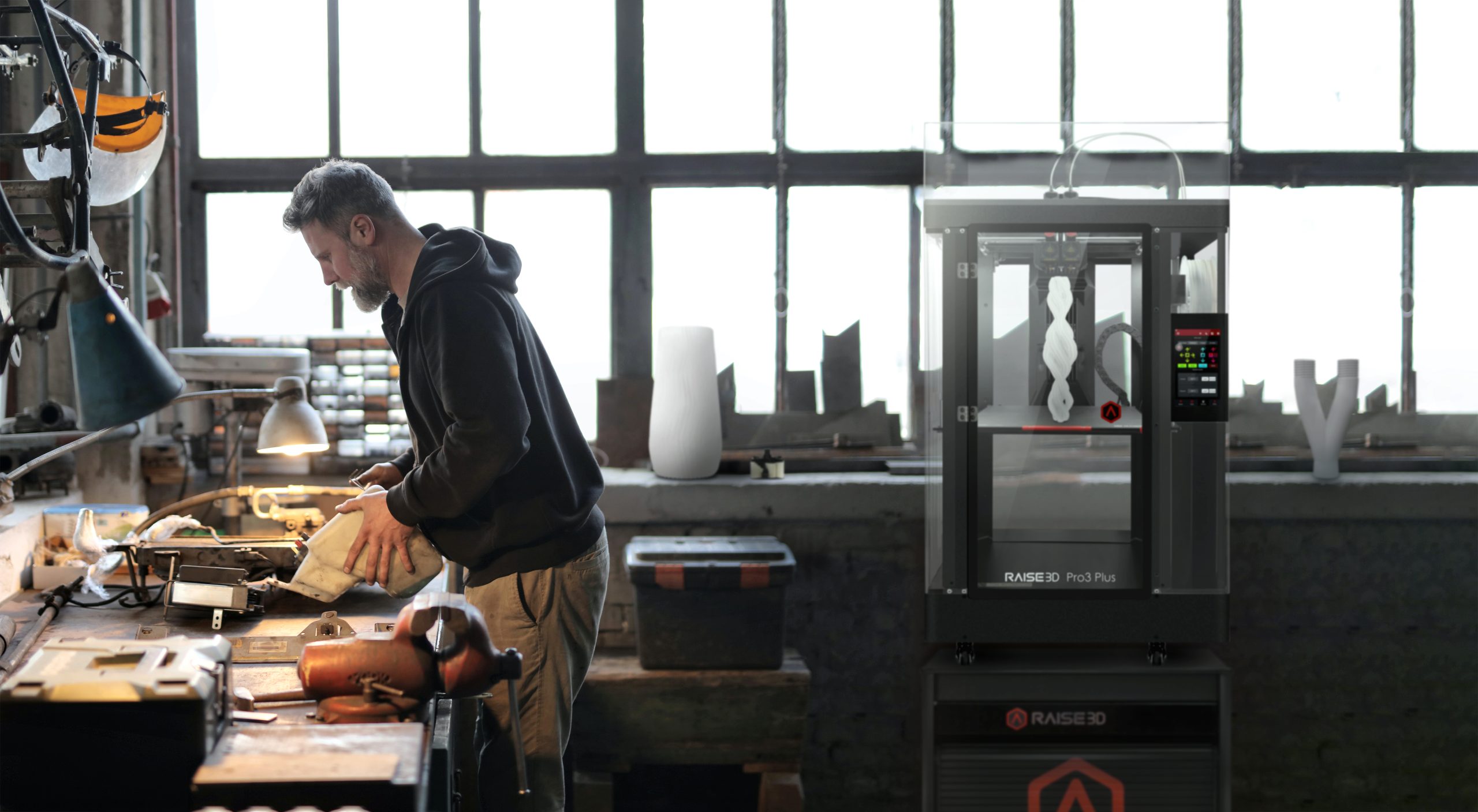
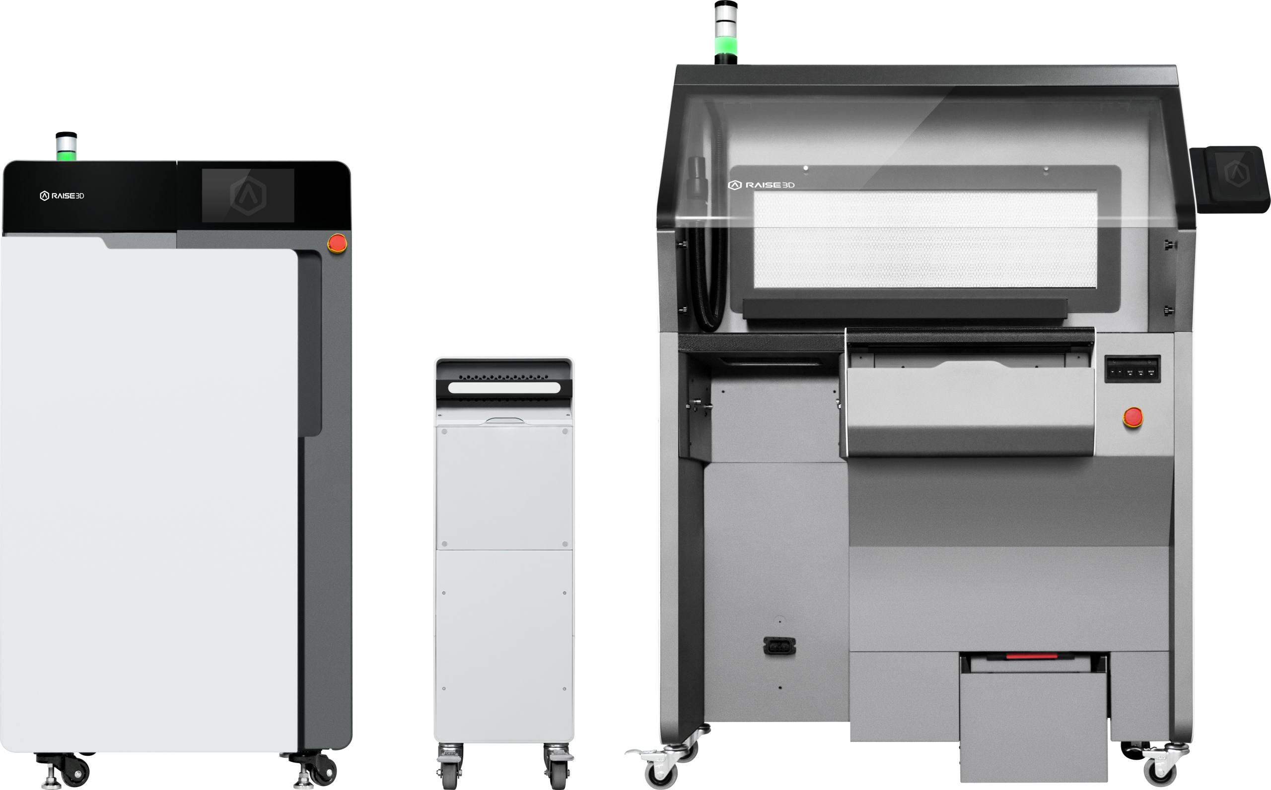
          The Raise3D Pro3 and Pro3 Plus are industrial FDM printers designed to support a broad range of applications, from functional prototyping to manufacturing jigs, fixtures, and production tooling. Their robust construction and dual-extrusion architecture provide the flexibility needed to tackle diverse projects with a single platform.

          Raise3D Pro3 & Pro3 Plus

          Build Volume

          • Pro3: 300 × 300 × 300 mm

          • Pro3 Plus: 300 × 300 × 605 mm

          The extended build height of the Pro3 Plus is particularly valuable when producing large components or maximizing the number of parts manufactured in a single print job.

          Compatible Materials

          FDM technology supports a wide variety of thermoplastics, including:

          • PLA

          • PETG

          • ABS

          • ASA

          • TPU

          • Nylon

          • Fiber-reinforced composites

          Raise3D also offers a portfolio of validated materials with optimized print profiles. This helps users achieve reliable and repeatable results with minimal setup.

          Third-party materials can also be used when specific application requirements demand it. This flexibility is a major advantage, although official Raise3D materials typically provide the most predictable and repeatable performance in production environments.

          Industries Served

          Manufacturing, automotive, aerospace, industrial design, and R&D teams all use the Pro3 series. Because of its versatility, organizations often rely on it when they want to support multiple applications without investing in several specialized machines.

          Pro3 Series Industries

          Why Is the Pro3 Series So Popular?

          One of the greatest strengths of the Pro3 platform is its ability to grow alongside an organization’s needs. The same machine can be used to validate a prototype, manufacture an assembly fixture, or produce a replacement maintenance component. This versatility, combined with broad material compatibility and dependable performance, has made the Pro3 one of the most widely adopted industrial FDM platforms available today.

          Raise3D E3: Productivity, Compactness, and Flexibility

          Not every organization needs larger parts. In many cases, the primary goal is to improve efficiency or make 3D printing accessible to a broader range of users.

          The Raise3D E3 was designed with this objective in mind.

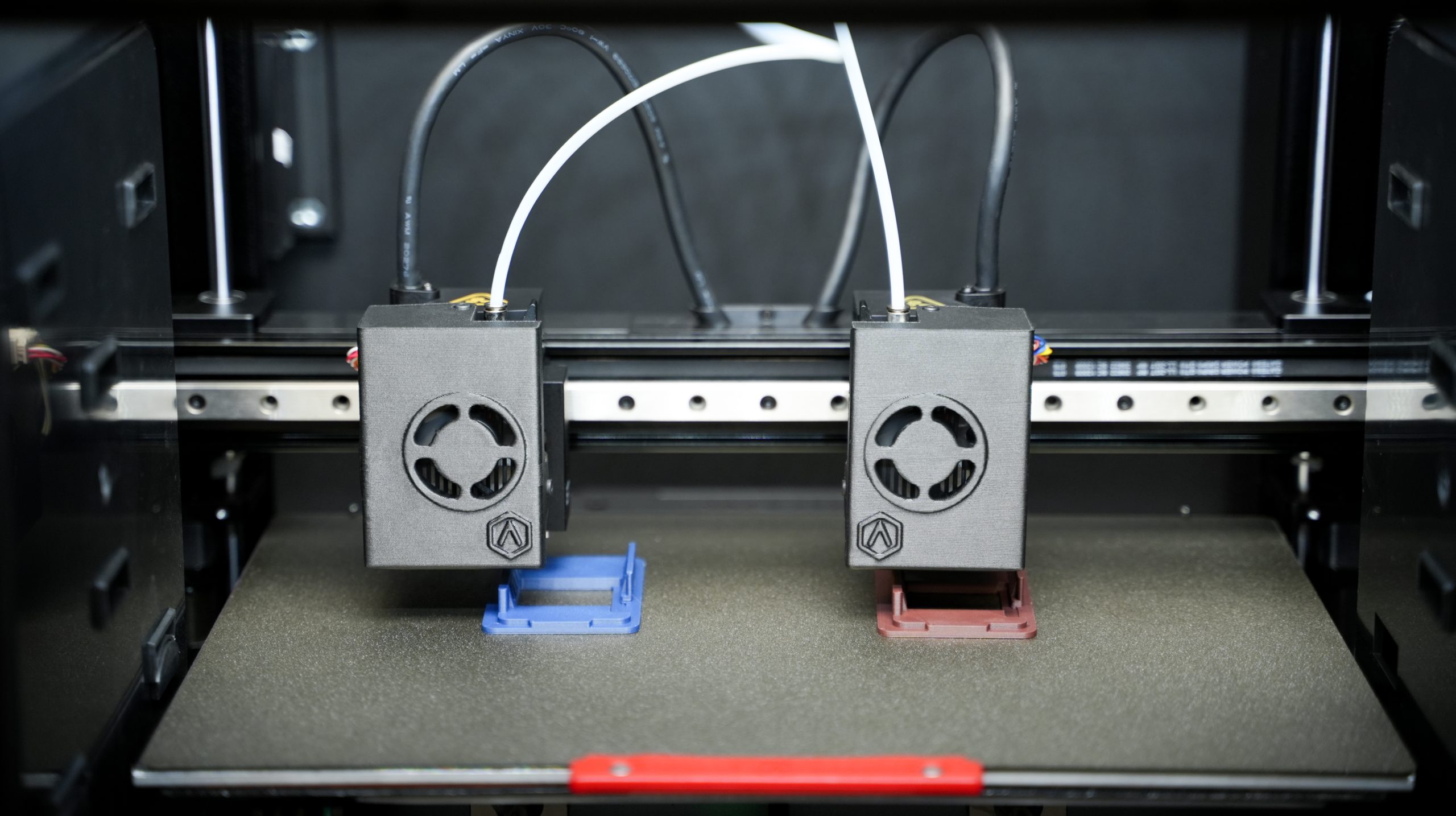
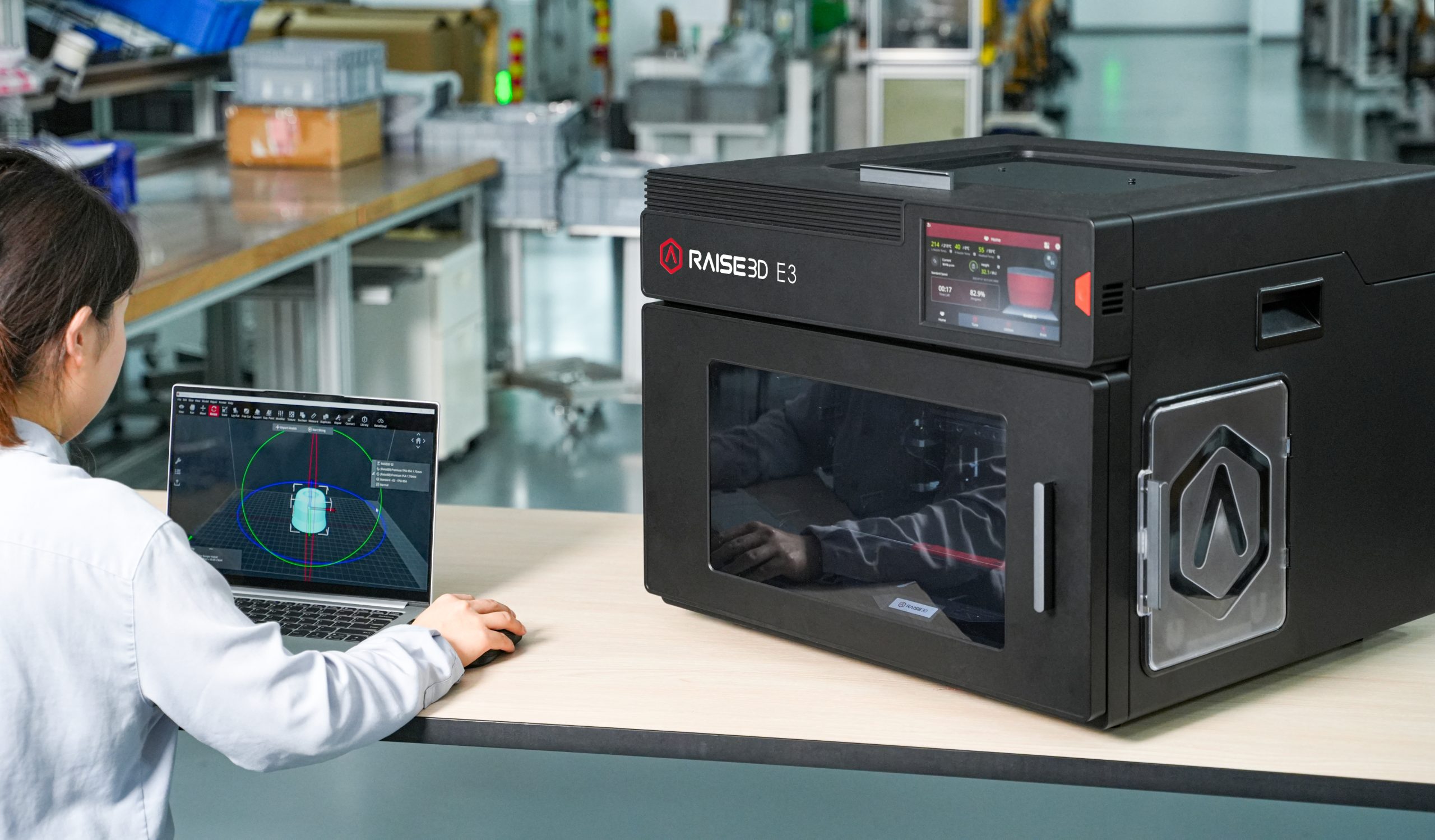
          Built around an Independent Dual Extruder (IDEX) architecture, the E3 features two print heads that operate independently. This enables duplication and mirror-printing modes that can significantly increase productivity for certain applications.

          Raise3D E3

          Build Volume

          330 × 240 × 240 mm

          Compatible Materials

          The E3 supports the major FDM material families:

          • PLA

          • PETG

          • ABS

          • ASA

          • TPU

          • Nylon

          • Engineering composites

          Like other Raise3D platforms, official Raise3D materials benefit from optimized print profiles while still allowing users the freedom to work with third-party materials when required.

          Industries and Environments

          The E3 is particularly well suited for engineering departments, research centers, product development teams, and educational institutions. Its compact footprint and ease of integration make it an excellent choice for laboratories, classrooms, technical training centers, and office environments.

          For organizations looking to expand access to 3D printing without deploying a dedicated production area, the E3 often represents an attractive and practical solution.

          Raise3D E3 Industries

          A Different Approach to Productivity

          Rather than focusing on larger build volumes, the E3 improves efficiency by maximizing machine utilization. Its IDEX architecture enables simultaneous production of multiple parts or duplicate prototypes, naturally accelerating development cycles and reducing turnaround times for engineering teams.

          Raise3D DF2: When Precision Matters Most

          Some applications demand a level of accuracy and surface quality that traditional FDM technologies cannot always achieve.

          This is where the Raise3D DF2 stands out.

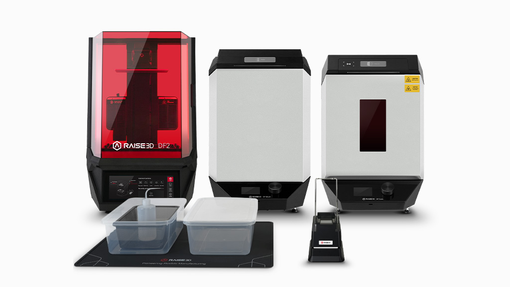
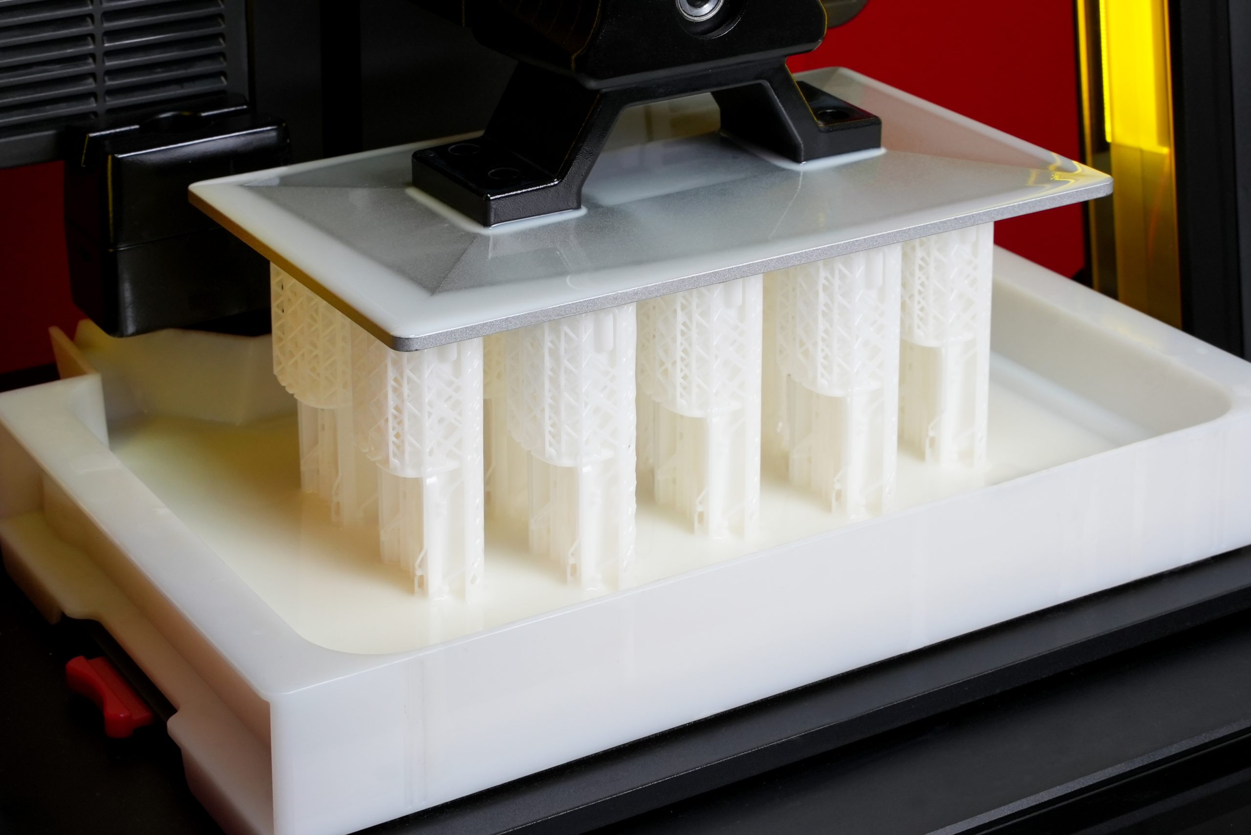
          Powered by DLP technology, the DF2 delivers highly detailed parts with exceptional surface finish and excellent repeatability, making it ideal for applications where precision is critical.

          Raise3D DF2

          Build Volume

          120 × 68 × 300 mm

          Compatible Materials

          The DF2 supports a range of photopolymer resins, including:

          • Rigid resins

          • Engineering resins

          • Flexible resins

          • Application-specific specialty resins

          The DF2 ecosystem is built around validated materials and qualified process parameters, helping users achieve consistent results from one print to the next.

          Industries Served

          The DF2 is commonly used in medical, dental, industrial design, and research and development environments. It also supports specialized manufacturing applications where dimensional accuracy and surface quality are critical requirements.

          One documented example is 3DPMolds, which uses the DF2 to accelerate the production of molds for low-volume plastic injection molding, demonstrating how resin technologies continue to expand into practical industrial applications.

          A Platform Built for Accuracy

          The DF2 is designed for organizations where surface finish, fine details, and dimensional precision play a central role in the manufacturing process. When these factors become critical, DLP technology offers advantages that are difficult to match with conventional FDM systems.

          DF2 Scene

          Raise3D RMS 220: Moving Toward Production

          In some cases, additive manufacturing is no longer used simply to develop products, but to manufacture them directly.

          The Raise3D RMS 220 was created for exactly this purpose.

          Based on Selective Laser Sintering (SLS) technology, the RMS 220 produces parts from polymer powder without the need for support structures. This enables greater design freedom and allows users to efficiently fill the build chamber with multiple parts in a single production cycle.

          Raise3D RMS 220

          Build Volume

          220 × 220 × 350 mm

          Compatible Materials

          The RMS 220 is designed for industrial polymer powders such as:

          • PA11

          • PA12

          Officially supported materials benefit from validated process parameters that help ensure repeatability and production stability.

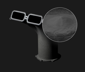
          Raise3D RMS 220 Compatible Materials

          Industries Served

          The RMS 220 is intended for manufacturers, automotive companies, aerospace organizations, and businesses looking to adopt additive manufacturing as a production technology.

          Documented use cases include companies such as Kinboshi and LutraCAD, both of which have integrated the RMS 220 into industrial workflows involving the production of end-use and customized parts.

          A Step Toward Manufacturing

          SLS technology represents an important milestone in the adoption of additive manufacturing. The absence of support structures, combined with strong mechanical properties and exceptional design freedom, makes it particularly well suited for low- to medium-volume production.

          Why Choose Solidxperts?

          Selecting an industrial 3D printer involves much more than comparing technical specifications.

          The real challenge is identifying the technology that will deliver the greatest value for your specific applications and business objectives.

          At Solidxperts, we help organizations navigate this decision-making process. Our role extends beyond supplying equipment. We support our customers through needs analysis, technology selection, installation, training, and ongoing technical support.

          This approach enables businesses to adopt additive manufacturing in a structured, scalable, and results driven manner.

          What’s the Next Step?

          With the Pro3 and Pro3 Plus, E3, DF2, and RMS 220, Raise3D offers a diverse portfolio of additive manufacturing solutions that address a wide range of industrial requirements.

          Some organizations need a versatile platform to accelerate product development. Others require higher precision, greater design freedom, or increased production capabilities. Each technology serves a different purpose, and the application itself should always guide the decision.

          One of Raise3D’s greatest strengths lies in its balance of performance, flexibility, and accessibility. These platforms enable organizations to integrate 3D printing into their operations without the complexity or investment often associated with more specialized technologies.

          At Solidxperts, we believe a successful additive manufacturing project starts long before a machine is installed. It begins with a clear understanding of production goals, materials, operational constraints, and long-term business objectives.

          Whether your goal is to accelerate prototyping, optimize production processes, or explore new manufacturing possibilities, our team is ready to help identify the technology best suited to your reality.

          Because in industrial 3D printing, the best solution is not necessarily the most advanced one. It is the one that best meets your needs.

          Looking to go further?


          Lilian Beatrix

          Additive Manufacturing Specialist

          X_green_halo

          Any questions? Need help? Ask one of our experts.

          Whether you’re ready to get started or just have a few more questions, you can contact us toll-free:
            SOLIDWORKS Design vs Onshape: Which CAD Platform Is Right for Your Team?

            BLOG

            SOLIDWORKS Design vs Onshape: Which CAD Platform Is Right for Your Team?

            [techtips_featured_image_shortcode]

            Choosing a CAD platform is a bigger decision than just comparing modeling tools.

            Today, engineering teams need to think about collaboration, data management, cloud connectivity, licensing flexibility, training requirements, and even AI-powered productivity tools. Whether you’re replacing an older CAD system, evaluating cloud CAD for the first time, or planning for future growth, the platform you choose will impact your workflow for years.

            Two of the most common options being evaluated today are SOLIDWORKS Design and Onshape.

            Both are professional CAD solutions that support parametric modeling and offer cloud connected workflows. But they are built around very different philosophies.

            Let’s break down the differences.

            Quick Answer: SOLIDWORKS Design or Onshape?

            If your team wants a mature, industry-standard CAD platform with powerful desktop performance, extensive engineering tools, flexible licensing options, and access to the broader 3DEXPERIENCE ecosystem, SOLIDWORKS Design is typically the stronger choice.

            If your priority is a browser only CAD environment with simplified deployment and built-in cloud collaboration, Onshape may be worth considering.

            The right answer depends on your team’s workflows, product complexity, and long-term goals.

            What Is SOLIDWORKS Design?

            SOLIDWORKS Design is the latest evolution of the SOLIDWORKS portfolio.

            It combines the CAD environment engineers have trusted for decades with modern cloud services, collaboration tools, revision management, and AI-powered capabilities through the 3DEXPERIENCE platform.

            Today, organizations can choose between multiple deployment approaches:

            SOLIDWORKS Design Single-User License

            A named-user license connected directly to cloud services and the 3DEXPERIENCE platform.

            Benefits include:

            • Access from multiple devices

            • Built-in cloud collaboration

            • Cloud file and revision management

            • Continuous updates

            • AI-enabled cloud services and tools

            SOLIDWORKS Design Device License

            A machine-based license designed for organizations that prefer traditional deployment methods.

            Benefits include:

            • Local installation control

            • Machine-based activation

            • Multi-user workstation environments

            • Optional cloud connectivity

            • Support for controlled IT deployment strategies

            Both licensing options provide access to Cloud Services and future expansion into the broader 3DEXPERIENCE ecosystem.

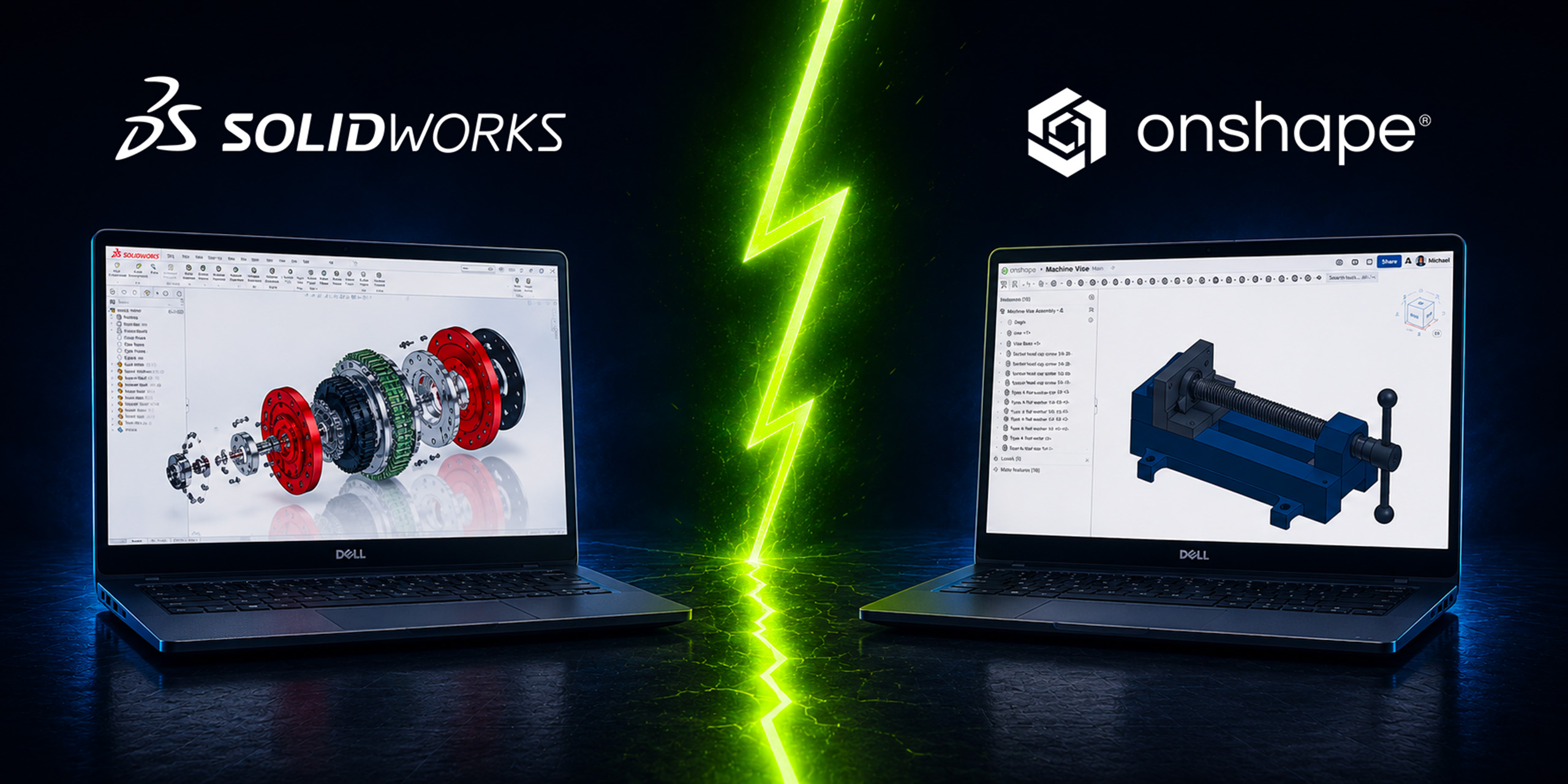
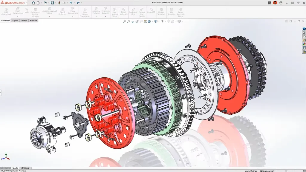
            Comparison of SOLIDWORKS Design and Onshape interfaces to help teams choose the right CAD platform.SOLIDWORKS CAD Modeling Environment

            What Is Onshape?

            Onshape is a fully browser based CAD platform.

            Unlike traditional desktop CAD, there is no local installation. Users access their CAD environment through a web browser, and all data is stored in the cloud.

            Because the platform is cloud-native, Onshape provides:

            • Real time collaboration

            • Built-in version history

            • Browser based access

            • Automatic updates

            • Simplified IT deployment

            This makes it attractive for distributed teams, startups, educational institutions, and organizations looking to avoid workstation management.

            Side-by-side comparison of SOLIDWORKS and Onshape highlighting key features for engineering teams.

            Onshape CAD Modeling Environment

            SOLIDWORKS Design vs Onshape: The Biggest Differences

            Modeling Experience

            Both platforms use modern parametric modeling workflows.

            However, SOLIDWORKS Design still offers a more mature and feature rich modeling environment for many engineering use cases.

            Areas where SOLIDWORKS continues to excel include:

            • Large assemblies

            • Weldments

            • Routing

            • Drawings and detailing

            • Manufacturing documentation

            • Simulation integration

            • CAM integration

            • Advanced surfacing workflows

            For many engineers, SOLIDWORKS remains the benchmark for production ready mechanical design.

            Onshape delivers a modern modeling experience and continues to evolve rapidly, but some organizations transitioning from mature desktop CAD environments may find certain advanced workflows less developed.

            Performance

            This is where deployment philosophy matters.

            SOLIDWORKS Design

            Most CAD calculations happen locally on workstation hardware.

            Advantages:

            • Excellent performance on complex assemblies

            • Direct access to GPU resources

            • Better support for demanding engineering workloads

            • Less dependence on internet speed during modeling

            Onshape

            All modeling calculations occur on cloud infrastructure.

            Advantages:

            • Lower workstation requirements

            • Easy access from almost any device

            • Consistent performance across users

            For engineering teams working on large products, machinery, manufacturing equipment, or highly detailed assemblies, local workstation performance still offers significant advantages.

            Data Management

            Historically, data management was a major differentiator.

            Today, the gap is much smaller.

            Onshape

            Includes cloud-based data management by default.

            Users benefit from:

            • Version history

            • Branching workflows

            • Built-in collaboration

            • Cloud storage

            SOLIDWORKS Design

            Includes Cloud Services and can scale directly into the 3DEXPERIENCE platform.

            Organizations can start with:

            • Share and Markup

            • Store and Revise

            • Collaborative Spaces

            • Cloud revision management

            And later expand into:

            • Product lifecycle management (PLM)

            • Change actions

            • Governance workflows

            • Enterprise collaboration

            This creates a growth path from basic collaboration all the way to enterprise level product development.

            What About SOLIDWORKS xDesign?

            This is an important distinction that often gets overlooked.

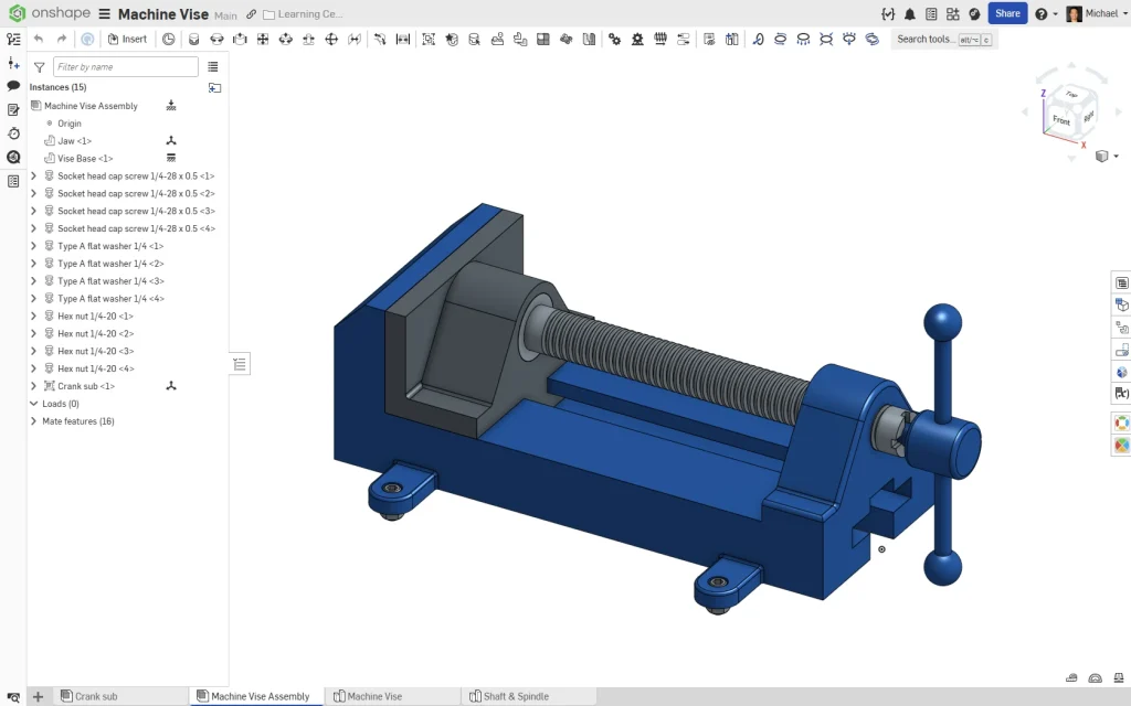
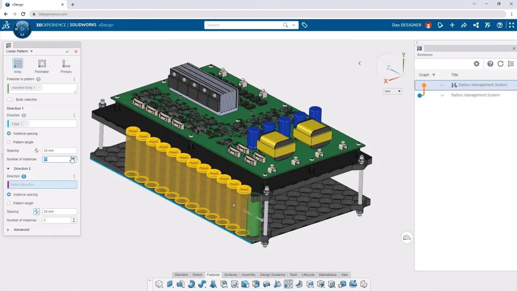
            When comparing browser-based CAD, the most direct comparison is often SOLIDWORKS xDesign versus Onshape, not SOLIDWORKS Design versus Onshape.

            SOLIDWORKS xDesign is Dassault Systèmes’ cloud-native design solution, running entirely in a web browser with no local installation required. It combines modeling, collaboration, lifecycle management, and cloud storage directly within the 3DEXPERIENCE platform.

            Overview of SOLIDWORKS Design and Onshape showing differences in workflow and collaboration features.

            SOLIDWORKS xDesign Modeling Environment

            For organizations that like the flexibility of browser-based CAD but want to stay within the SOLIDWORKS ecosystem, xDesign is often worth evaluating alongside Onshape.

            Many companies ultimately adopt a hybrid strategy:

            • SOLIDWORKS Design for advanced mechanical design

            • SOLIDWORKS xDesign for cloud-native collaboration and conceptual work

            • 3DEXPERIENCE for data management and lifecycle control

            AI Features: SOLIDWORKS vs Onshape

            AI is becoming part of every CAD discussion, but it’s important to separate practical tools from marketing buzzwords.

            Neither platform has a “design my product” button.

            Instead, both focus on productivity improvements.

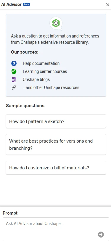
            AI in Onshape

            Onshape currently offers AI Advisor, an AI-powered assistant designed to answer questions and guide users through workflows using Onshape documentation and training resources as its knowledge base.

            AI Advisor can:

            • Answer workflow questions

            • Recommend best practices

            • Surface documentation

            • Provide troubleshooting guidance

            • Deliver contextual assistance inside the platform

            Importantly, Onshape states that AI Advisor does not currently generate designs or make engineering decisions.

            Visual comparison of SOLIDWORKS Design and Onshape focused on team collaboration and cloud capabilities.

            Onshape AI Advisor

            AI in SOLIDWORKS

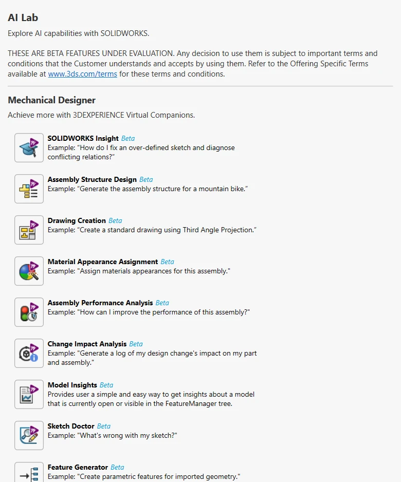
            SOLIDWORKS has been expanding its AI roadmap aggressively through both desktop and cloud-connected tools.

            Recent AI capabilities include:

            • Auto-Generate Drawings

            • Command Predictor

            • Fastener Recognition

            • Assembly Performance Evaluator

            • Material Appearance Manager

            • BREP-to-Parametric CAD conversion

            • Design Change Impact analysis

            • PLM Model Insights

            • AURA AI Assistant

            Rather than acting as a documentation assistant, many of these tools directly interact with engineering workflows and CAD data.

            The goal isn’t replacing engineers. It’s reducing repetitive work, accelerating documentation, improving performance, and helping teams make decisions faster.

            Illustration comparing SOLIDWORKS Design and Onshape to help determine the best CAD solution for design teams.

            SOLIDWORKS AI Lab

            Which Platform Is Better for Growing Companies?

            This is often the most important question.

            For startups prioritizing fast deployment and simple browser access, Onshape can be an attractive option.

            For companies expecting growth, increasing product complexity, manufacturing integration, simulation requirements, or future PLM adoption, SOLIDWORKS Design often provides a more scalable path.

            One of the biggest advantages of the SOLIDWORKS ecosystem is that organizations don’t need to commit to everything on day one.

            You can start with:

            • SOLIDWORKS Design

            • Cloud Services

            • Basic collaboration

            Then gradually expand into:

            • PDM

            • PLM

            • Simulation

            • Manufacturing

            • Electrical

            • Cloud-native design

            • AI-driven workflows

            Without changing CAD platforms.

            Why work with Solidxperts?

            Choosing software is only part of the project.

            Implementation, training, data management strategy, and user adoption are often what determine whether a deployment succeeds.

            At Solidxperts, we work with organizations every day that are evaluating:

            • SOLIDWORKS Design

            • SOLIDWORKS xDesign

            • Cloud Services

            • 3DEXPERIENCE

            • PDM and PLM solutions

            • CAD migration projects

            Whether you’re moving from another CAD platform, modernizing your data management strategy, or exploring AI-enabled workflows, our team can help you build a roadmap that fits your reality not just a software brochure.

            The goal isn’t simply choosing a CAD tool.

            It’s building a design environment that will still make sense five years from now.

            Looking to go further?


            Michael Habrich

            3DEXPERIENCE Specialist

            X_green_halo

            Any questions? Need help? Ask one of our experts.

            Whether you’re ready to get started or just have a few more questions, you can contact us toll-free:
              SWOOD 2026: Key New Features to Discover

              BLOG

              SWOOD 2026: Key New Features to Discover

              [techtips_featured_image_shortcode]

              SWOOD 2026: Design with more freedom, automate further, and produce faster

              The wood and furniture manufacturing industry is evolving quickly. Manufacturers are under constant pressure to shorten lead times, increase product personalization, overcome the shortage of skilled labor, and improve profitability. In this context, digital tools play an increasingly strategic role.

              With SWOOD 2026, EFICAD continues its vision of an integrated digital chain where design, manufacturing, and data management work together to accelerate processes while reducing manual interventions.

              This new release brings significant improvements across the entire SWOOD suite: SWOOD Design, SWOOD CAM, SWOOD Nesting, and SWOOD Center. More than just an update, SWOOD 2026 directly addresses the current challenges faced by manufacturers in the woodworking, cabinetry, commercial furniture, and bespoke fit-out sectors.

              Today’s challenges in wood manufacturing

              Before diving into what’s new, it’s important to understand the issues companies face today:

              • Growing demand for customized products

              • Reduced delivery lead times

              • Difficulty recruiting and training specialized resources

              • Increasing complexity of architectural projects

              • Need to integrate ERP, MES, and CNC equipment

              • Ongoing pursuit of greater productivity

              The new features in SWOOD 2026 were developed specifically to address these realities.

              SWOOD Design 2026: more freedom for complex projects

              Manufacturers of bespoke furniture know that atypical projects often pose the greatest design challenges. SWOOD Design 2026 introduces several improvements that make it easier to create customized products without increasing model complexity.

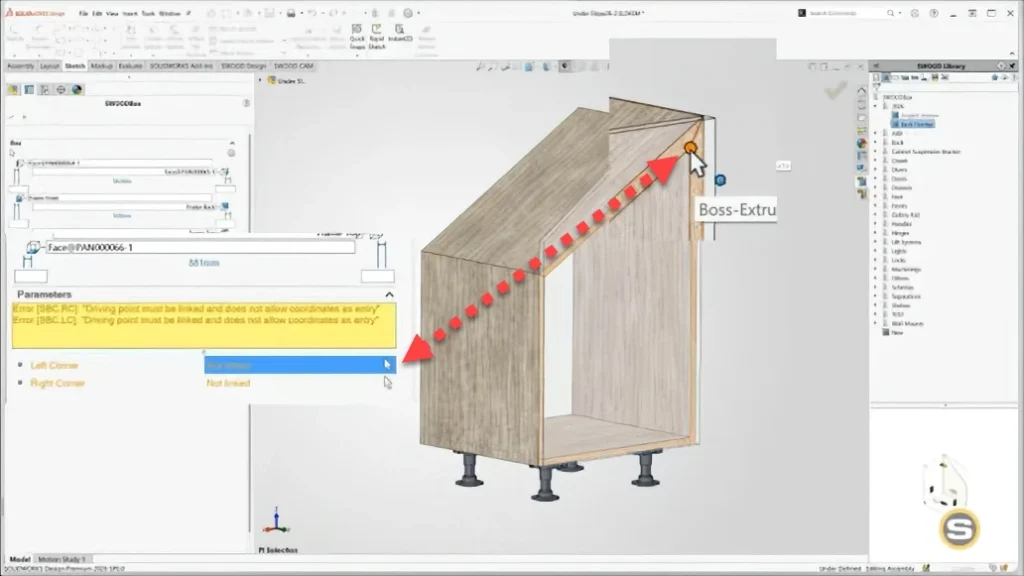
              1. SWOOD Box supports non-rectangular geometries

              Traditionally, standard furniture relies on simple, rectangular geometries. However, modern projects often require more complex shapes:

              • Under-stair furniture

              • Vehicle fit-outs

              • Built-ins under sloped ceilings

              • Custom architectural installations

              Thanks to the new Point parameter in SWOOD Box, you can now position and intelligently constrain components according to non conventional geometries.

              Benefits

              • Fewer specialized configurations

              • More flexible libraries

              • Better reuse of existing models

              • Faster development of parametric catalogs

              Overview of new features in SWOOD 2026 for woodworking design and manufacturing

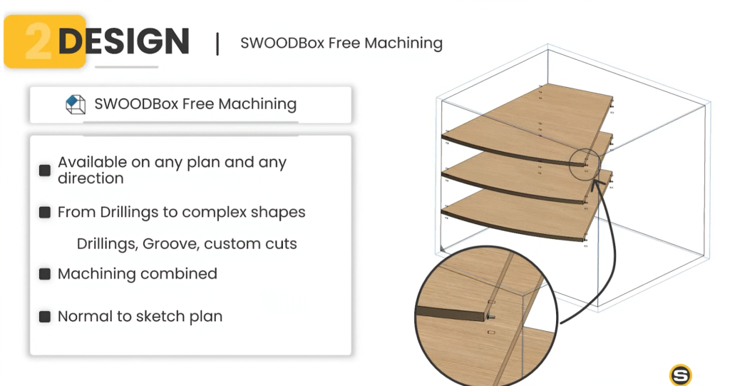
              2. Free Machining in SWOOD Box

              Manufacturing rarely follows rules perfectly aligned with a model’s standard CAD planes. With the new Free Machining feature, machining operations can now be defined according to the actual orientation of a sketch.

              This improvement enables:

              • Better consistency between design and manufacturing

              • Simplified handling of angled panels

              • Reduced manual adjustments in CAM

              3. Multilingual libraries

              For companies working with multiple plants, subsidiaries, or international partners, library management can quickly become complex. SWOOD 2026 now allows SWOOD Box parameters to be displayed in multiple languages.

              Outcome

              • Simpler rollout of corporate standards

              • Improved collaboration across international teams

              • Fewer misunderstandings

              Key highlights of SWOOD 2026 updates for CAD and woodworking workflows

              SWOOD CAM 2026: automation reaches a new level

              For many manufacturers, the bottleneck is no longer design but the preparation of CNC programs. SWOOD CAM 2026 introduces features that significantly reduce manual interventions.

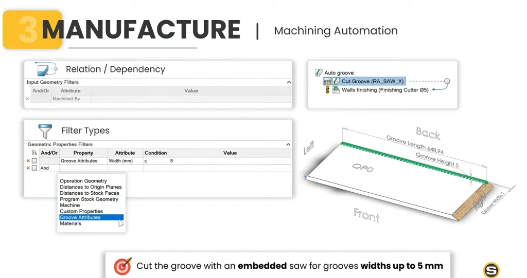
              1. CAM Filters: one of the most important new features in SWOOD 2026

              The new CAM Filters allow you to automatically assign machining strategies based on different criteria:

              • Materials

              • Geometry

              • Machines

              • SOLIDWORKS properties

              • Manufacturing properties

              • Post-processors

              Why it matters

              Rather than creating specific rules for every situation, manufacturers can develop reusable and scalable manufacturing logic.

              The benefits are immediate:

              • Reduced programming time

              • Standardized machining methods

              • Lower risk of errors

              Updated user interface and improvements introduced in SWOOD 2026

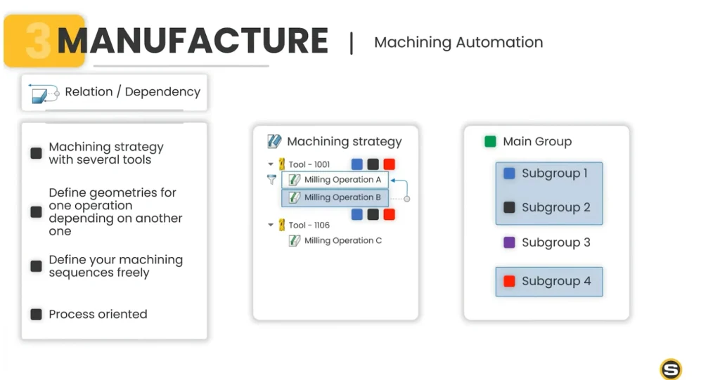
              2. Relationships between CAM operations

              Another major improvement concerns communication between machining operations. Operations can now automatically share already-identified geometries.

              For example:

              • A drilling operation can pass references to a secondary operation

              • A groove can be automatically recognized by other strategies

              • Specialized connectors can be processed more efficiently

              Direct impact

              • More robust automation

              • Less duplication of rules

              • Simplified maintenance of CAM libraries

              New cabinet design tools and features available in SWOOD 2026

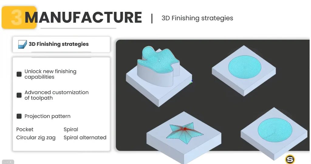
              3. New 3D machining strategies

              Manufacturers producing complex parts will also benefit from new toolpath strategies:

              • 3D roughing

              • Projected finishing

              • Spiral

              • Alternating spiral

              • Circular zig-zag

              • Cavity machining

              Outcome

              • Better surface finish quality

              • Optimized machining times

              • More efficient use of modern CNC machines

              CNC machining improvements and automation features in SWOOD 2026

              SWOOD Nesting 2026: more control over panel optimization

              With material costs remaining high, panel optimization is essential. SWOOD Nesting 2026 delivers greater stability in the handling of nests.

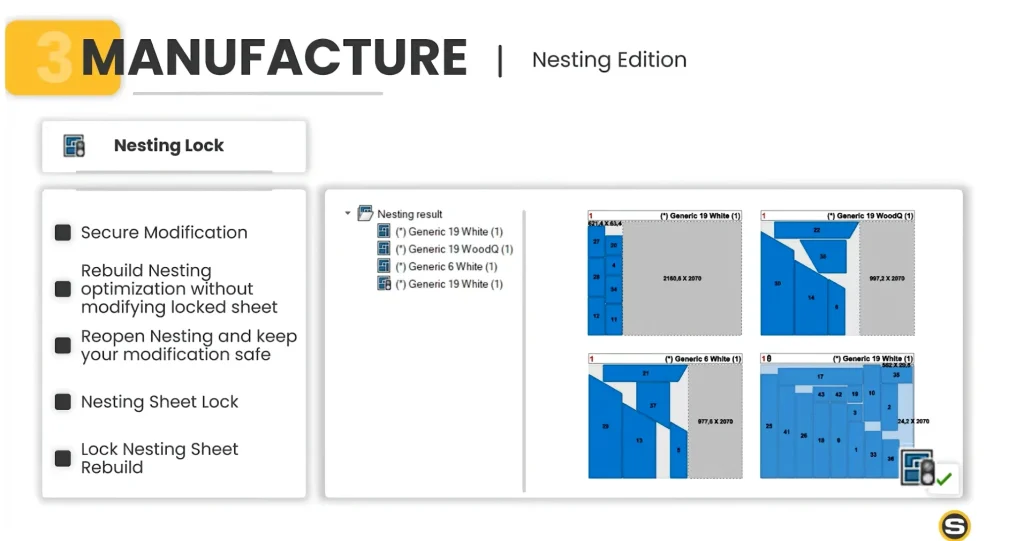
              1. Nesting Lock

              Users can now lock an optimization result to prevent accidental modification.

              Advantages

              • Protection of validated decisions

              • Greater control over the production process

              • Lower risk of unintentional reorganization

              Enhanced woodworking workflow and productivity tools in SWOOD 2026

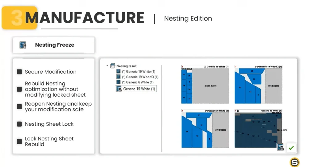
              2. Nesting Freeze

              This feature goes even further. CAM edits and adjustments made after optimization can be retained even when the project is updated.

              Benefits

              • Simplified revision management

              • Protection of work already completed

              • Fewer unnecessary reworks

              Automation features in SWOOD 2026 designed to improve design efficiency

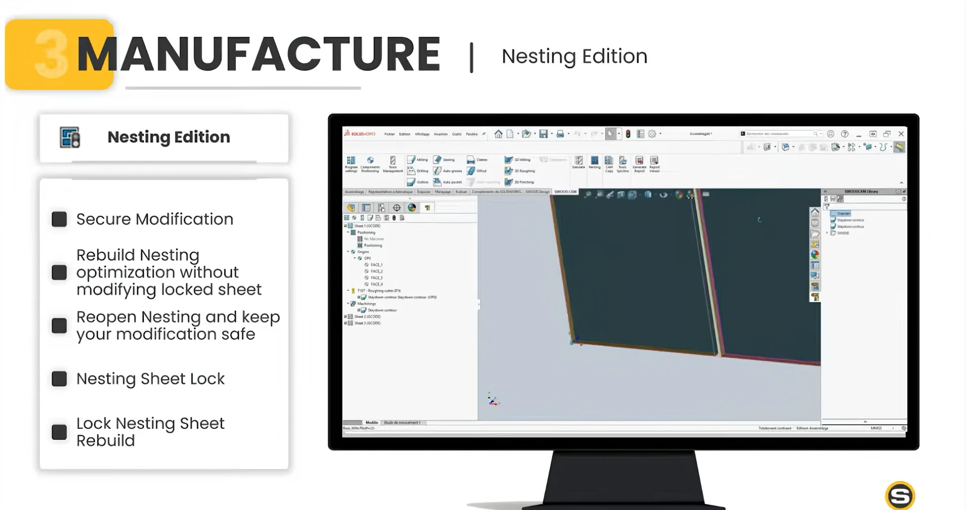
              3. Smart nesting updates

              Manufacturers rarely work on frozen projects. With SWOOD 2026, nesting assemblies can be reopened and updated while preserving previous adjustments.

              This improvement is especially useful for:

              • Evolving projects

              • Commercial furniture

              • Make-to-order environments

              Updated material libraries and components included in SWOOD 2026

              SWOOD Center 2026: connecting engineering to the shop floor

              The value of a modern manufacturing solution also depends on its ability to communicate with other enterprise systems. SWOOD Center continues this mission with several important additions.

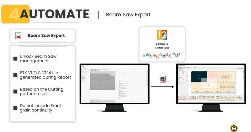
              1. PTX export for panel saws

              SWOOD now supports PTX formats 1.14 and 1.21. This improvement makes it easier to integrate with many production machines used in the industry.

              Outcome

              • Less manual data entry

              • Lower risk of errors

              • Smoother data flow between systems

              Performance upgrades and faster processing in SWOOD 2026 software

              2. Batch document generation

              Users can now automatically generate:

              • Drawings

              • Reports

              • Panel lists

              • Hardware lists

              • Production documents

              Impact

              • Significant time savings

              • Standardized documentation

              • Higher team productivity

              Enhanced 3D wood modeling capabilities introduced in SWOOD 2026

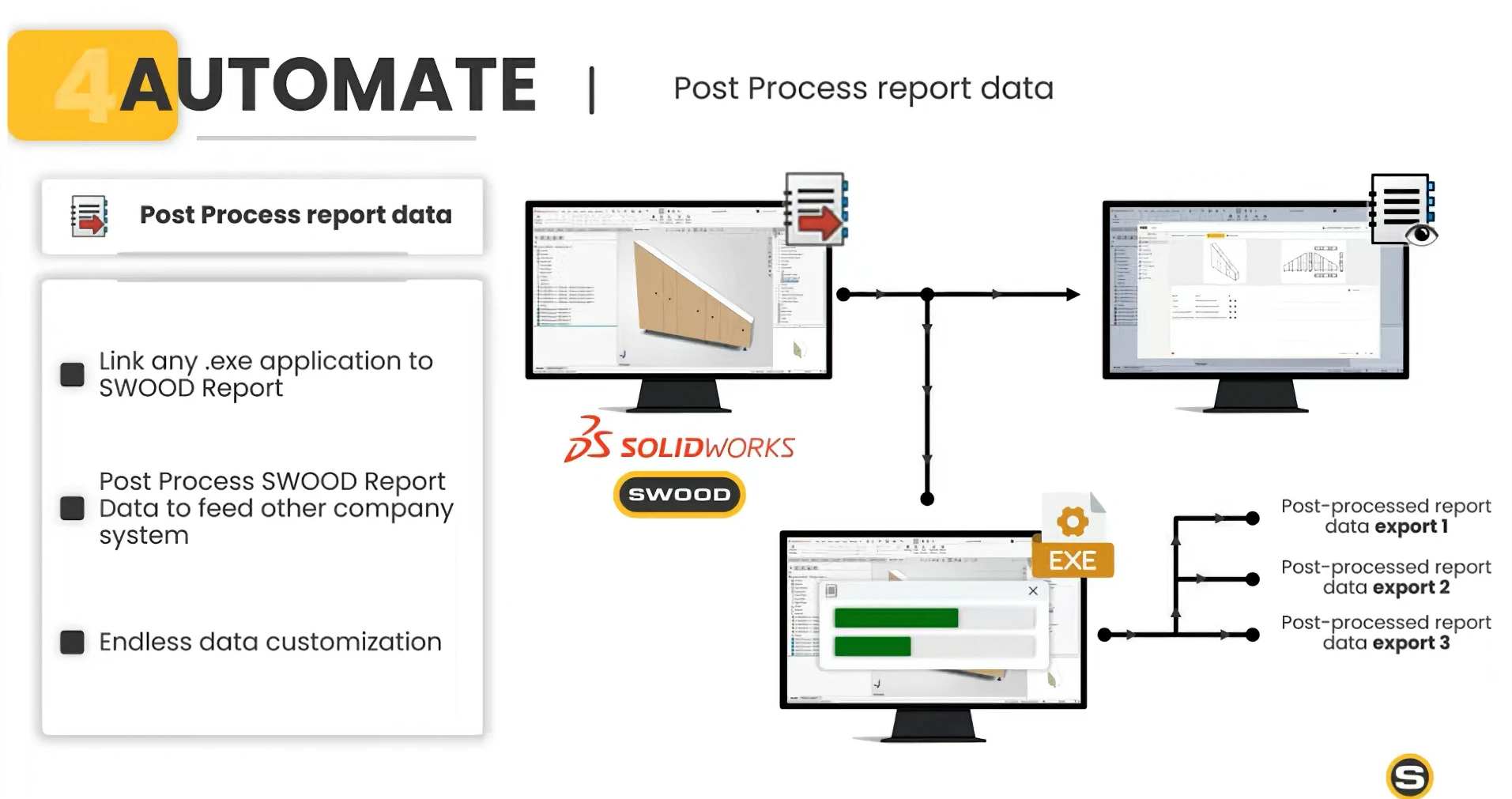
              3. Enterprise integration automation

              SWOOD Center can now automatically launch external applications from generated reports. This capability opens the door to advanced integrations with:

              • ERP

              • MES

              • Planning tools

              • Custom internal systems

              New assembly tools for woodworking projects in SWOOD 2026

              The vision behind SWOOD 2026

              Looking across all the new features, a clear trend emerges. SWOOD is no longer just aiming to speed up design or CNC programming. The platform now strives to create complete digital continuity between engineering and production.

              This strategy rests on four pillars:

              1. Design without constraints

              The new SWOOD Box capabilities let you tackle increasingly complex projects without multiplying models and configurations.

              2. Automate further

              CAM Filters and inter-operation relationships reduce reliance on individual know-how and foster standardization.

              3. Optimize materials

              The new SWOOD Nesting functions protect completed work while simplifying revision management.

              4. Connect systems

              New features in SWOOD Center strengthen integration between engineering software, ERPs, and production equipment.

              Why consider upgrading to SWOOD 2026?

              For companies already using SWOOD, this release is a major opportunity to increase their level of automation. For manufacturers currently evaluating their digital processes, SWOOD 2026 clearly demonstrates that it is possible to:

              • Reduce preparation time

              • Standardize manufacturing methods

              • Simplify management of complex projects

              • Maximize material usage

              • Improve cross-department integration

              In a context where every minute saved and every avoided error has a direct impact on profitability, the new features in SWOOD 2026 offer concrete tools to improve overall business performance.

              Explore SWOOD 2026 with SOLIDXPERTS

              Want to assess the impact of SWOOD 2026 on your design and manufacturing processes? The SOLIDXPERTS team can help you:

              • Analyze your current methods

              • Identify automation opportunities

              • Demonstrate SWOOD 2026’s new features

              • Develop a deployment strategy tailored to your manufacturing reality

              Contact our SWOOD specialists today to discover how SWOOD 2026 can accelerate your digital transformation and increase your production efficiency.


              Alain

              Alain Provost

              Senior Technical Sales Executive

              X_green_halo

              Any questions? Need help? Ask one of our experts.

              Whether you’re ready to get started or just have a few more questions, you can contact us toll-free:
                Managing Roles on the 3DEXPERIENCE Platform

                BLOG

                Managing Roles on the 3DEXPERIENCE Platform

                [techtips_featured_image_shortcode]

                More and more organizations are moving to the 3DEXPERIENCE platform to streamline collaboration, improve data management, and connect their teams. One of the most important pieces of a successful rollout is understanding how Roles work, how they’re assigned, and how licensing is managed.

                In this article, we’ll walk through the full lifecycle of Role management, from inviting members to your tenant to assigning Roles individually or by group.

                Platform Administrator Access

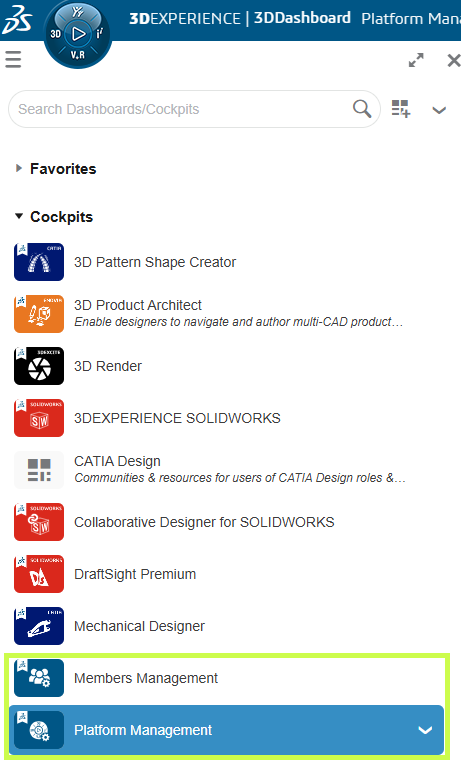
                The steps outlined below require you to be a 3DEXPERIENCE Platform Administrator for your company tenant.

                If you don’t see the Platform Management or Members Management dashboards:

                • Reach out to your internal 3DEXPERIENCE administrator, or

                • If you are the admin and still can’t access them, contact your technical support team to help resolve the issue.

                Screenshot showing how to manage user roles and permissions on the 3DEXPERIENCE platform.

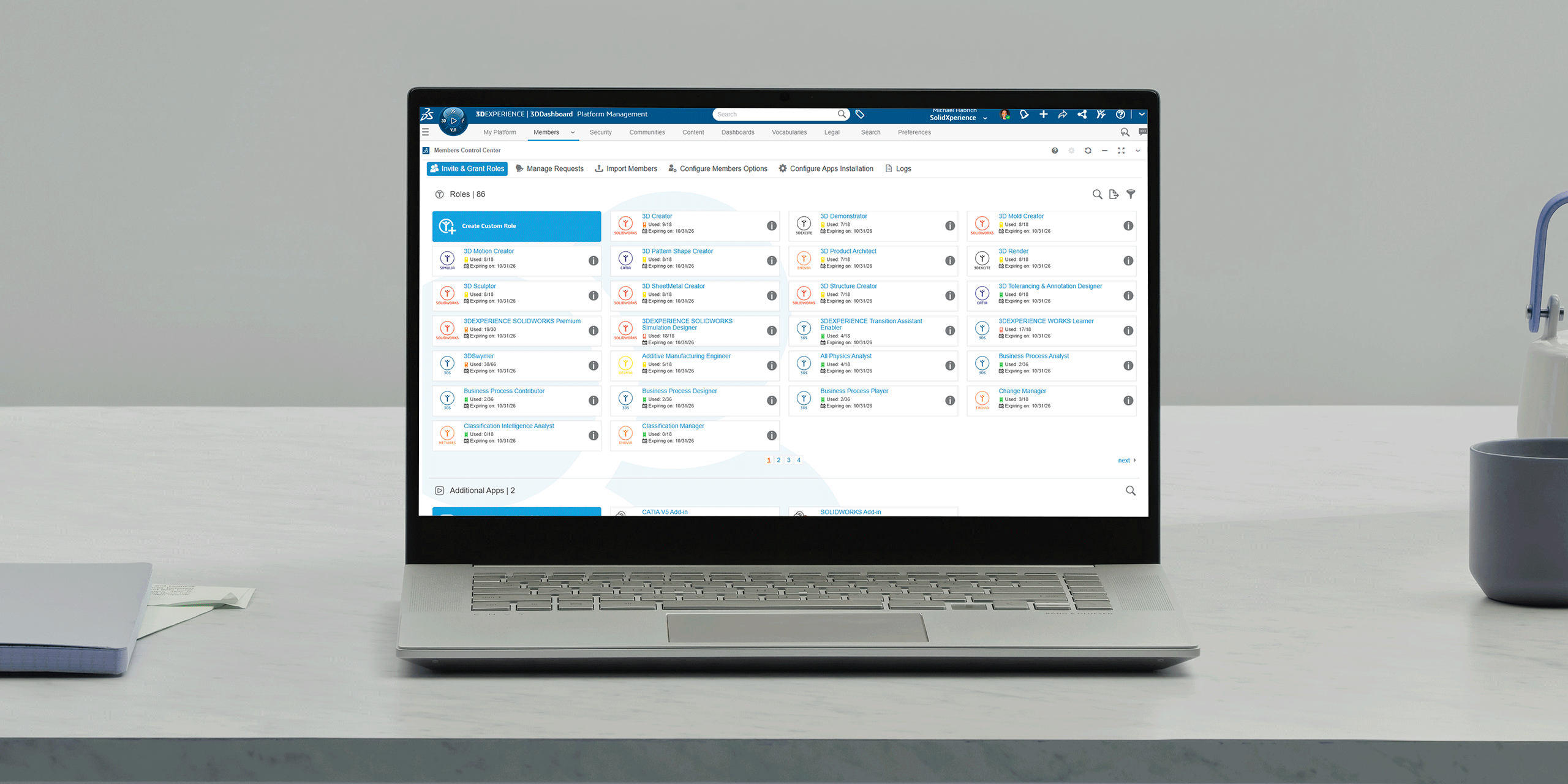
                Members Control Center

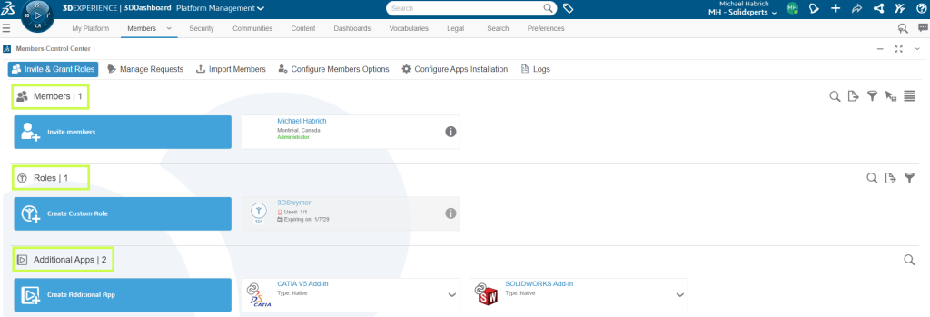
                Once you have the appropriate permissions, open the Members Control Center from:

                • The Members Management Dashboard, or

                • The Members tab within the Platform Management Dashboard

                This is your main workspace for:

                • Reviewing existing members

                • Viewing available Roles and license counts

                • Managing additional apps assigned to the tenant

                3DEXPERIENCE platform interface displaying tools for managing user roles, access rights, and responsibilities.

                Licensing Options (Before You Assign Roles)

                Before assigning any Roles, it’s a good idea to review the licensing behavior for your tenant.

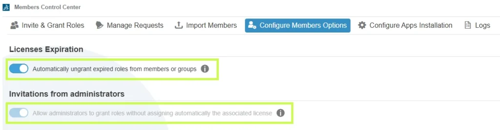
                From the Members Control Center, select Configure Members Options.

                There are two key settings to review:

                1. License Expiration

                We strongly recommend enabling Automatically ungrant expired roles from members or groups.
                This ensures that:

                • Roles are automatically removed when licenses expire

                • Users don’t encounter access errors due to expired licensing

                2. Invitations from Administrators

                The option Allow administrators to grant roles without assigning automatically the associated license controls how external users access Roles:

                • Enabled: external users can use their own licenses

                • Disabled: licenses must come from your tenant

                Taking a moment to configure these options upfront can prevent licensing issues down the road.

                View of the 3DEXPERIENCE platform showing role configuration and assignment for team members.

                Understanding Member Role Assignments

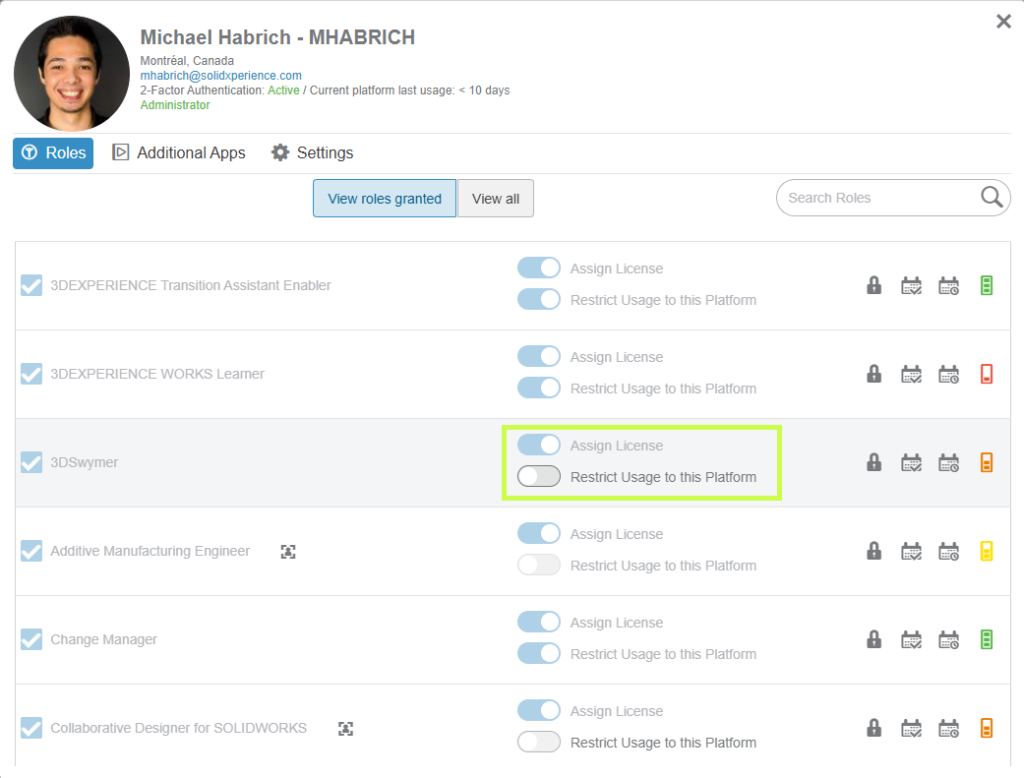
                To see how these settings affect a specific user:

                1. Go back to Invite & Grant Roles

                2. Select Details for a member

                Each Role represents a purchased license and unlocks access to specific apps and capabilities.

                Key options include:

                Assign License:

                • Enabled → license is consumed from your tenant
                • Disabled → external user uses a license from another tenant

                Restrict Usage to the Platform:

                • Enabled → license can only be used on this tenant
                • Disabled → license can be used across tenants

                User management dashboard in the 3DEXPERIENCE platform used to assign, modify, and monitor platform roles.

                Assigning Roles to Members

                To assign Roles:

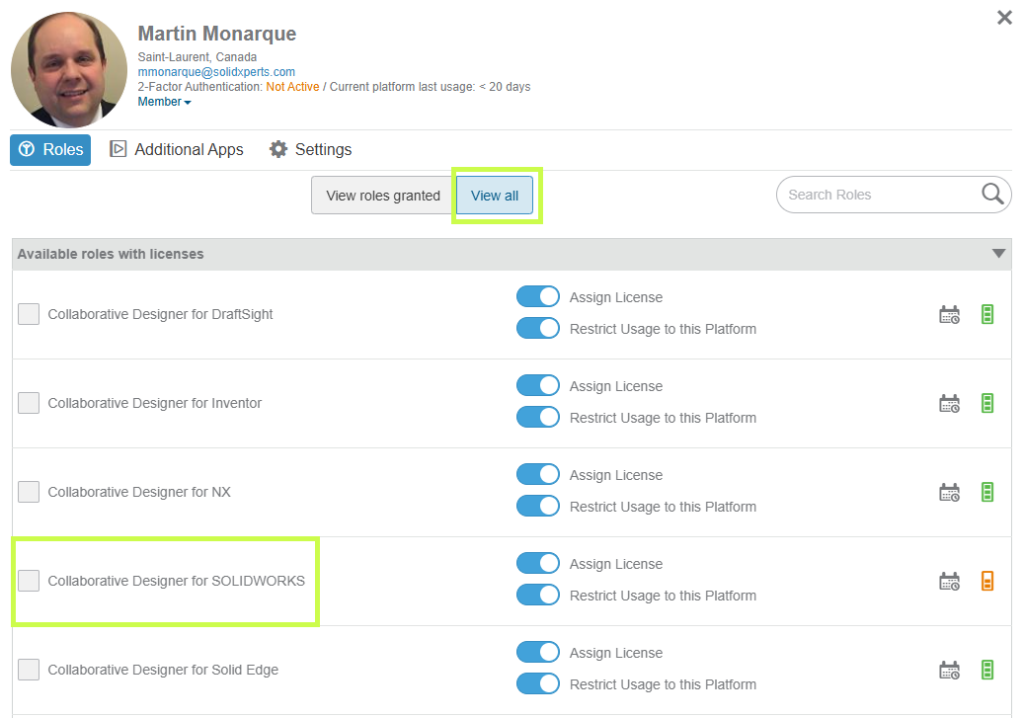
                1. Click View All to see every available Role

                2. Use search if needed, by Role name or trigram (for example, UES for Collaborative Designer for SOLIDWORKS)

                3. Set the licensing options for the Role

                4. Select the checkbox to grant it

                3DEXPERIENCE administration tools used to manage user roles and access permissions.

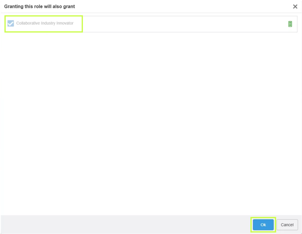
                If a Role requires prerequisites, you’ll be prompted to add them automatically. Simply confirm to proceed.

                3DEXPERIENCE platform screen illustrating the organization of user roles and permissions within a company.

                Inviting New Members

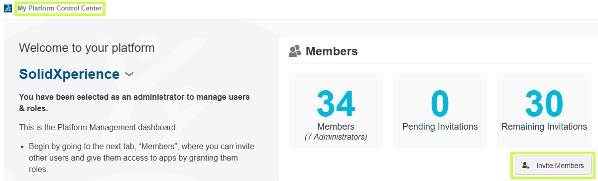
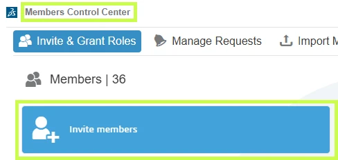
                Roles can also be assigned during the invitation process. You can invite users from:

                • My Platform Control Center

                Centralized management of user roles, licenses, and access permissions within the 3DEXPERIENCE environment.

                • Members Control Center

                3DEXPERIENCE administration interface used to define user roles, responsibilities, and access levels.

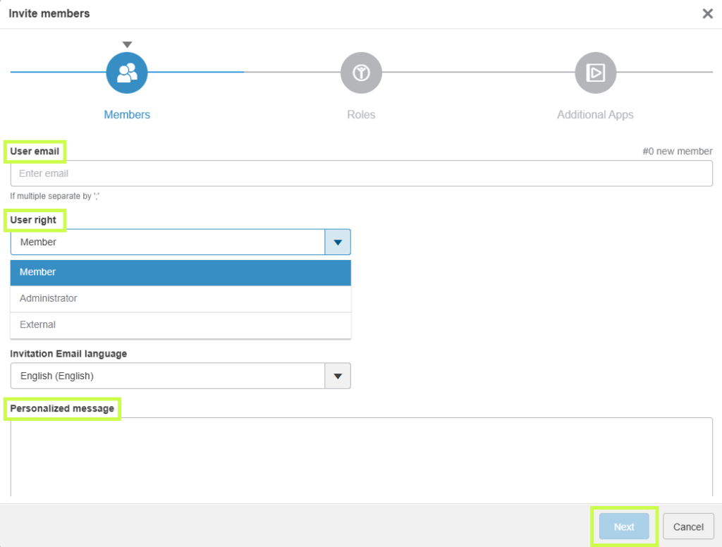
                Steps to Invite a Member:

                1. Click Invite Member

                2. Enter one or more email addresses

                3. Choose user rights:

                • Member
                • Tenant Administrator (always a good idea to have a backup admin)
                • External User

                4. Optionally include a personal message

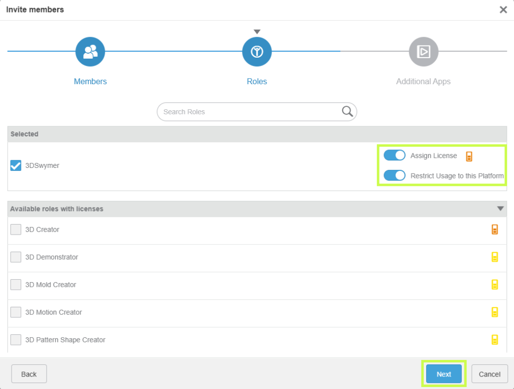
                5. Click Next to select Roles

                User management on the 3DEXPERIENCE platform with role assignment and application access control.

                Choose the Roles to assign, review any prerequisite requirements, and configure licensing options if needed.

                3DEXPERIENCE administration panel showing user profile management and associated role configuration.

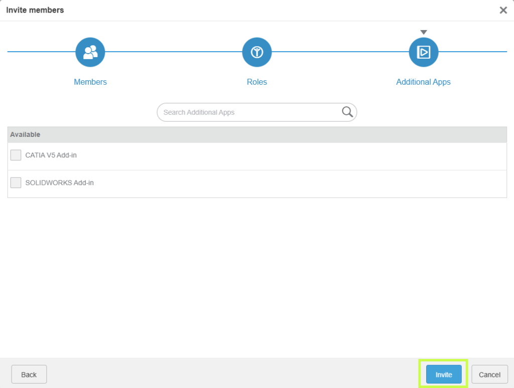
                In the final step, select any available apps and click Invite to complete the process.

                3DEXPERIENCE interface for user role management with options to assign and update permissions.

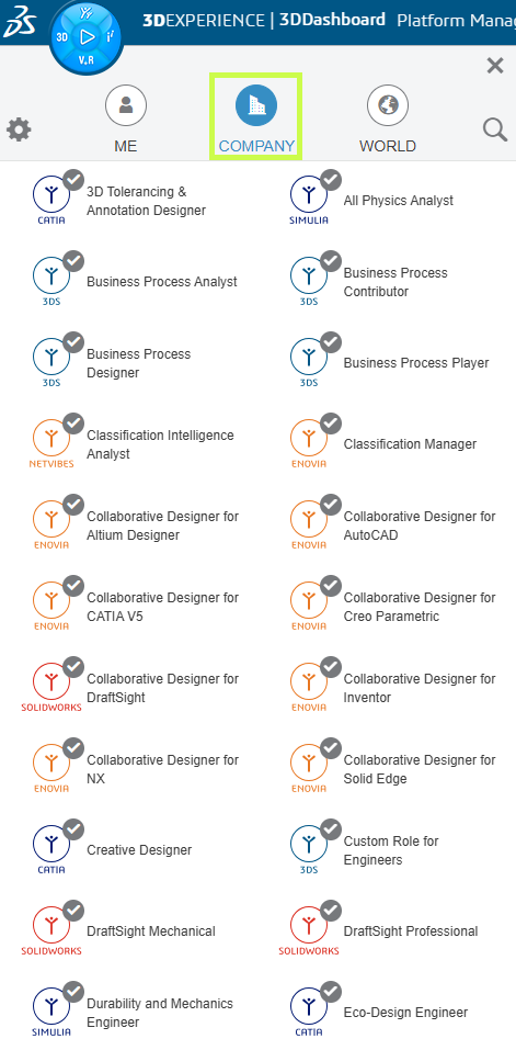
                Requesting Roles (User-Initiated)

                Users can also request Roles directly from the platform:

                1. Open the Compass

                2. Go to Company

                3DEXPERIENCE administration screen displaying a user list and their assigned roles configuration.

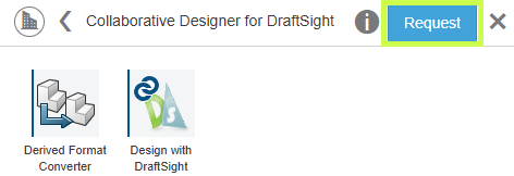
                3. Select a Role and click Request

                3DEXPERIENCE interface displaying role and access management settings for platform users.

                The administrator will receive both a platform notification and an email.

                Approving Role Requests:

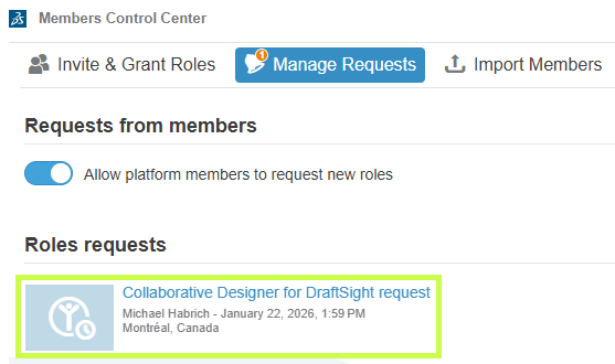
                1. Open the Members Control Center

                2. Select Manage Requests

                3. Open the request tile

                3DEXPERIENCE configuration screen showing selection and assignment of user roles based on permissions.

                4. Click Accept to grant the Role

                3DEXPERIENCE administration interface showing user role management with filtering and assignment options.

                Assigning Roles Using Groups

                Groups are a powerful way to manage Roles at scale.

                Creating a User Group:

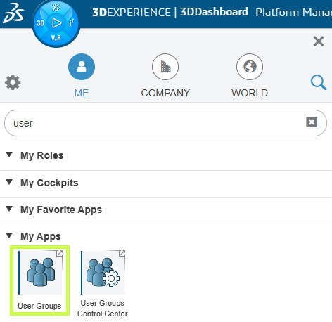
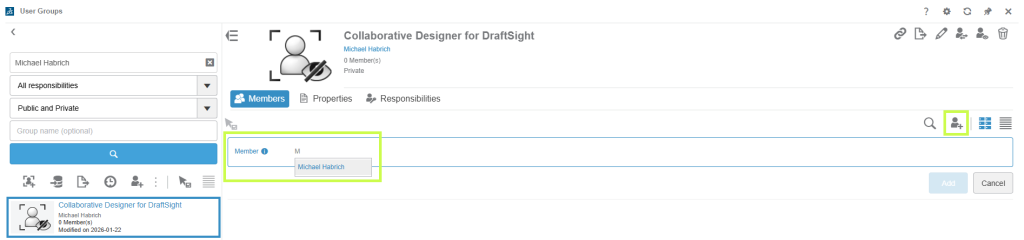
                1. Open the User Groups app (via the Compass)

                3DEXPERIENCE dashboard displaying available roles and their assignment to platform users.

                2. Click Create Group

                3DEXPERIENCE management screen showing role selection and customization of access rights for each user.

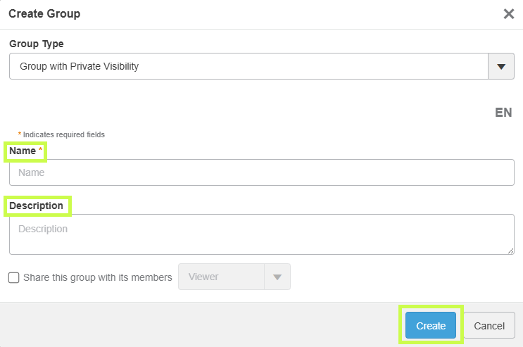
                3. Enter a name and description

                • Tip: name the group after the Role it will receive

                3DEXPERIENCE administration console for viewing, assigning, and managing user roles in a collaborative environment.

                4. Click Create

                5. Add members to the group and save

                3DEXPERIENCE interface showing user role management with search, filtering, and permission assignment options.

                Assigning Roles to a Group:

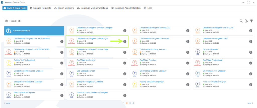
                1. Go to Members Control Center → Invite & Grant Roles

                2. Open Details for the desired Role

                3DEXPERIENCE interface displaying user role management with a preview of permissions associated with each role.

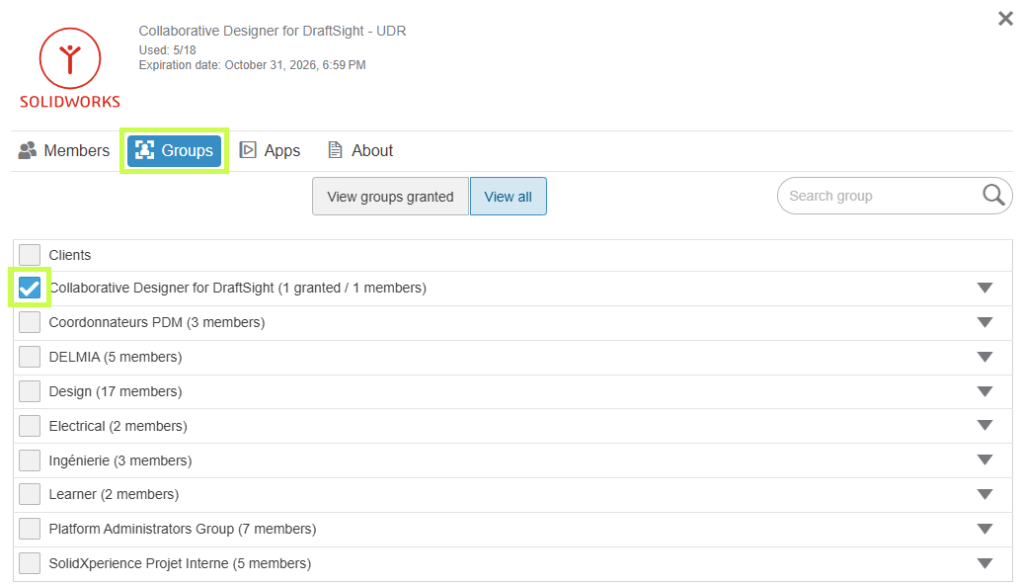
                3. Switch to the Groups tab

                4. Select the appropriate group and confirm any prerequisite Roles

                3DEXPERIENCE administration screen illustrating user role management and access rights structure within the platform.

                Any user added to the group will automatically receive the assigned Role.

                Removing Members from the Tenant

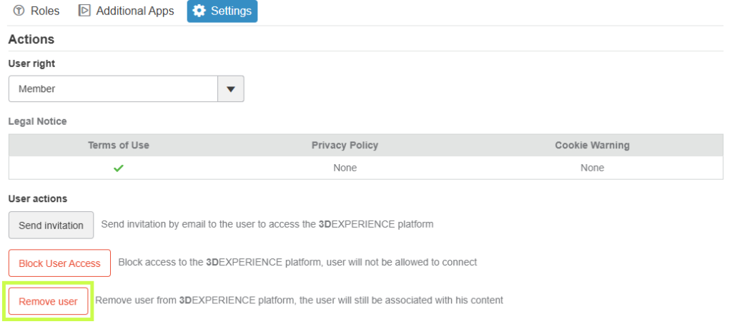
                When a user no longer needs access:

                1. Open the Members Control Center

                2. Select Details for the member

                3. Go to Settings

                4. Remove the user from the tenant

                3DEXPERIENCE user role management interface showing available roles and their assignment to organization members.

                Warning Make sure to remove any roles that have been assigned to that user before removing them from the platform to avoid any issues with future re-assignment.

                check mark button The best practice is to use User Groups to assign roles, that way you can simply remove a user from the User Group to remove their roles.

                Final Thoughts

                Managing Roles effectively is key to getting the most value from the 3DEXPERIENCE platform. With the right setup, you can ensure users have exactly the tools they need no more, no less while keeping licensing clean and manageable.

                Looking to go further?

                Your platform should work the way your team works and we’re here to help make that happen.


                Michael Habrich

                3DEXPERIENCE Specialist

                X_green_halo

                Any questions? Need help? Ask one of our experts.

                Whether you’re ready to get started or just have a few more questions, you can contact us toll-free:
                  FAQ: AI at the Core of SOLIDWORKS and 3DEXPERIENCE

                  BLOG

                  FAQ: AI at the Core of SOLIDWORKS and 3DEXPERIENCE

                  What is AI in SOLIDWORKS?

                  At its core, SOLIDWORKS AI refers to a set of intelligent capabilities that assist engineers by automating repetitive tasks, providing design guidance, and enabling workflow orchestration through built-in features and Virtual Companions that can be interacted with using natural language.

                  What AI features are currently available in SOLIDWORKS?

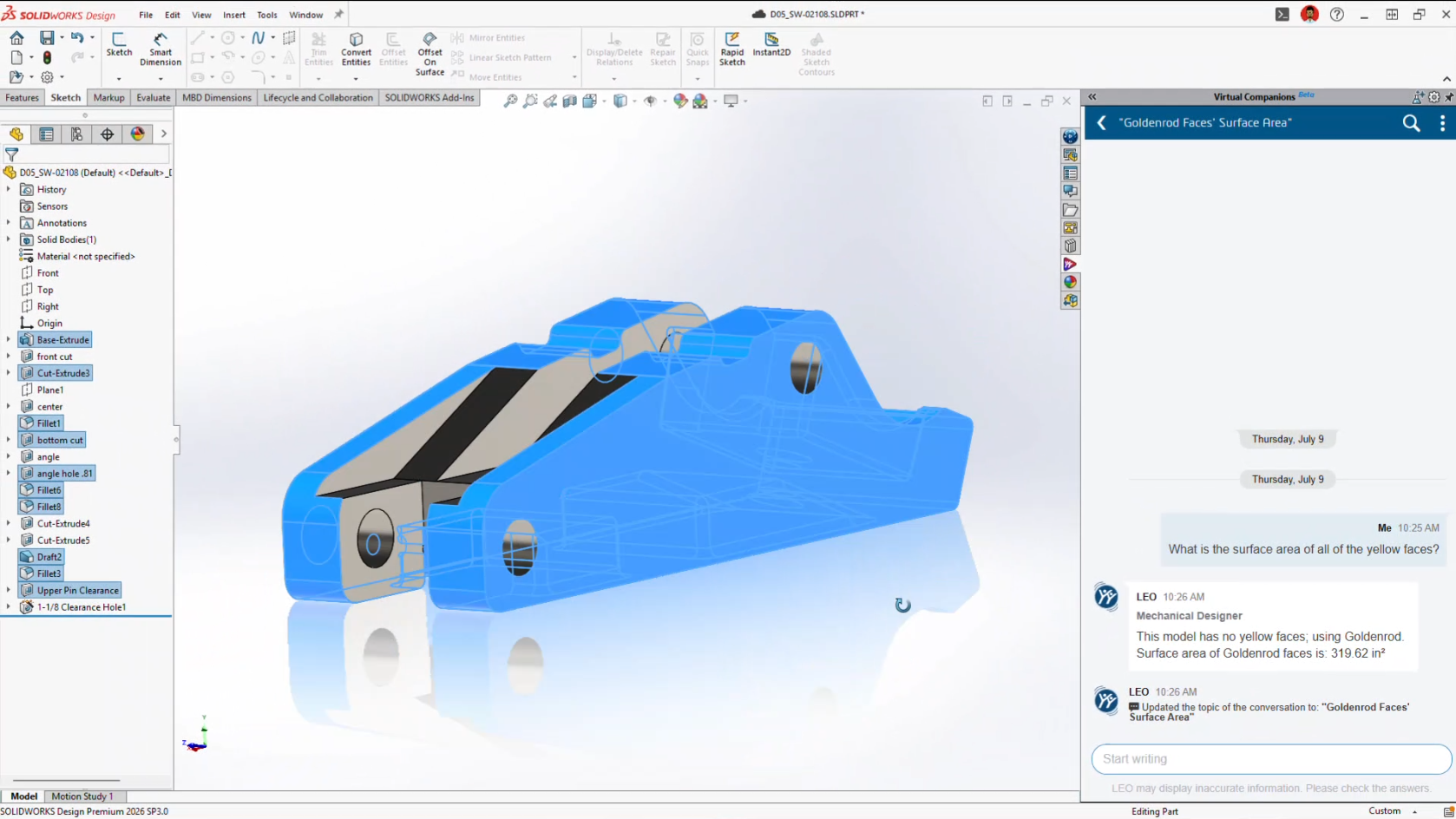
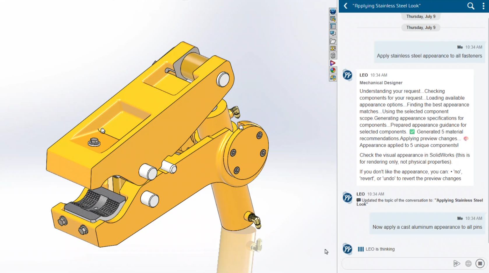
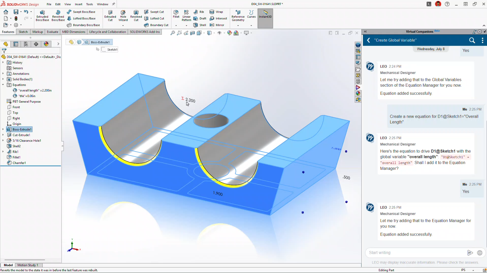
                  Currently, available capabilities include automated drawing generation, general design assistance through an interactive chat interface, command prediction, sketch analysis and repair, fastener recognition, and many additional features that are being rapidly developed and expanded.

                  Learn more about what’s available in SOLIDWORKS AI.

                  Stay up to date with the latest SOLIDWORKS Design features.

                  What is the difference between built-in AI features and Virtual Companions in SOLIDWORKS?

                  On one hand, built-in AI refers to machine learning-based capabilities that enhance existing design workflows. On the other hand, Virtual Companions are AI assistants that can be engaged using natural language to access knowledge and perform specific tasks. Both built-in AI features and Virtual Companions are available directly within the SOLIDWORKS Design user interface.

                  What are the roles of the new Virtual Companions?

                  Unlike generic conversational agents, our companions embody AI at the heart of engineering, grounded in physics and causality.

                  Name

                  Specialty

                  Example Application (E-Foil Wing)

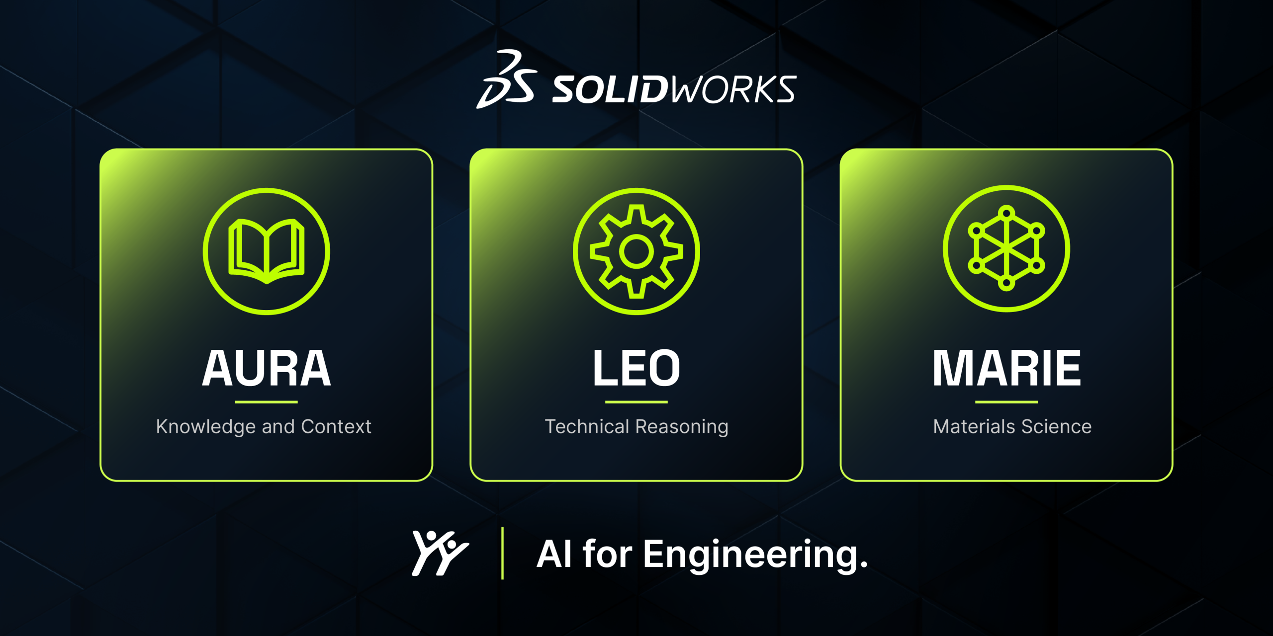
                  AURA

                  Knowledge and Context

                  Balances requirements for strength, lightweight construction, and water resistance (for example, choosing between carbon fiber and fiberglass).

                  LEO

                  Engineering Reasoning

                  Optimizes the strength-to-weight ratio using carbon composites, specifically unidirectional carbon fiber with epoxy resin for stiffness and fatigue resistance.

                  MARIE

                  Materials Science

                  Analyzes critical factors such as density (1.6 g/cm³), elastic modulus, and resistance to water-induced degradation.

                  How do these entities collaborate to optimize a project?

                  Innovation emerges from the combination of multiple perspectives. AURA explores the range of possibilities, MARIE grounds the project in rigorous materials science, and LEO ensures mechanical and manufacturing feasibility. Together, they help identify the optimal technical solution without compromising safety or manufacturability.

                  Why is the move to the Cloud essential for these new AI capabilities?

                  Knowledge extraction, deep data mining, and the execution of complex AI models require significant computing power. Cloud infrastructure is the only practical way to provide these resources flexibly and cost-effectively to organizations of all sizes.

                  Does SOLIDWORKS AI use customer data for training?

                  No. Customer data is not used to train AI models. Governance controls ensure the protection of intellectual property. You can learn more by visiting the 3DS Trust Center.

                  Can AI automatically create drawings?

                  Yes. SOLIDWORKS Design includes the ability to automatically generate 2D drawings by interacting with Virtual Companions using natural language. Drawings can be created according to specified standards, templates, and dimensioning schemes, helping accelerate the documentation process.

                  Can AI automate repetitive CAD tasks?

                  Yes. SOLIDWORKS AI automates repetitive engineering tasks such as drawing creation and assembly structure generation. Additional capabilities will continue to be introduced in future releases.

                  How does SOLIDWORKS AI protect intellectual property?

                  SOLIDWORKS AI ensures that customer intellectual property remains isolated and secure. Learn more about the specific security protocols by visiting the 3DS Trust Center.

                  How do I get started with AI in SOLIDWORKS?

                  Start by exploring the built-in AI capabilities and current Virtual Companion features available through the AI Lab task pane directly within SOLIDWORKS Design. Access to Virtual Companions requires Cloud Services to be enabled, which are included with every SOLIDWORKS Design license.

                  Can AI automatically fix CAD models?

                  AI can identify issues, explain errors, and suggest corrections. However, engineers remain responsible for reviewing and approving any modifications.

                  Will AI replace CAD designers and engineers?

                  No. AI helps automate repetitive tasks and uncover valuable insights, but engineers remain responsible for design intent, validation, and decision-making.

                  Want to Learn More?

                  Discover more tips and tutorials on our YouTube channel.

                  Explore best practices with our experts.

                  Or contact our team, we’re here to help you get the most out of your platform.


                  Benoit Bilodeau

                  Senior Solutions Architect

                  X_green_halo

                  Vous avez des questions ? Besoin d’aide ? Demandez à l’un de nos experts.

                  Que vous soyez prêt à commencer ou que vous ayez quelques questions supplémentaires, vous pouvez nous contacter sans frais :

                    Exporting Derived Outputs from the 3DEXPERIENCE Platform

                    BLOG

                    Exporting Derived Outputs from the 3DEXPERIENCE Platform

                    [techtips_featured_image_shortcode]

                    On the 3DEXPERIENCE platform, Derived Outputs such as PDFs, DXFs, STEP files, and other neutral formats are created from your CAD data for downstream use. These files are often shared with customers, suppliers, or partners who don’t have access to your platform tenant.

                    In this article, we’ll walk through a few practical ways to package and export Derived Outputs so they’re ready to send outside your organization.

                    Note: Dassault Systèmes provides general documentation on Derived Outputs. If you need help with setup, automation, or best practices, our technical support and implementation teams are always happy to help.

                    Choosing the Right Method

                    There are a couple of different apps and workflows you can use, each with its own advantages depending on:

                    • The number of files involved

                    • Whether you’re working with a single assembly or many

                    • How much cleanup you want to do afterward

                    Let’s take a look at the most common approaches.

                    Using the Product Explorer App

                    Method 1: Download Derived Outputs from a Single Assembly

                    1. Open the assembly in Product Explorer that already has Derived Outputs.

                    2. Select the top-level assembly node (it will highlight in blue).

                    User exporting derived output files from the 3DEXPERIENCE Platform interface.

                    3. Click the Information (i) icon in the lower toolbar.

                    Derived outputs including PDF, DXF, and STEP files displayed within the 3DEXPERIENCE Platform.

                    This opens the information side panel.

                    4. Navigate to Derived Formats.

                    Engineer preparing CAD-derived files for external sharing using the 3DEXPERIENCE Platform.

                    5. Click Download All Derived Outputs.

                    Export settings window for derived outputs on the 3DEXPERIENCE Platform.

                    6. Choose which 2D and 3D formats you want to include.

                    7. Name the ZIP file and click Download.

                    Downloading multiple derived outputs from the 3DEXPERIENCE Platform in a packaged folder.

                    If you’ve added multiple assemblies to Product Explorer, you’ll need to repeat this process for each one.

                    Trade-off:

                    • ✔ Clean output (Derived Outputs only)

                    • ✖ One assembly at a time

                    Method 2: Export Multiple Assemblies at Once

                    If you need to collect outputs from several assemblies or even unrelated parts, this method is much faster.

                    1. Add assemblies or parts to Product Explorer.

                    2. Select multiple items using checkboxes or Shift + Select.

                    3. Click Export As from the bottom toolbar.

                    Example of neutral CAD file formats generated from SOLIDWORKS data in 3DEXPERIENCE

                    4. Name the export, enable Expand All, and set the Derived Format Options.

                    5. Click Export.

                    Collaboration workflow using exported derived outputs from the 3DEXPERIENCE Platform.

                    A background job will start.

                    Once complete:

                    • A notification appears in the upper-right corner.

                    User selecting derived output files for export from a project dashboard in 3DEXPERIENCE.
                    • Click the notification to open the CAD Data Processor Monitoring app.

                    • Use the Download button to retrieve the ZIP file.

                    Exported PDF and STEP files ready for downstream manufacturing and review.

                    This ZIP will include both CAD files and Derived Outputs. To keep only the outputs, simply open the ZIP in Windows Explorer, sort by file type, and remove any files you don’t need.

                    Trade-off:

                    • ✔ Multiple assemblies or mixed files at once

                    • ✖ Manual cleanup required

                    Using the Bookmark Editor App

                    Method 1: Download Outputs from a Single Assembly

                    1. Locate the assembly in a bookmark (or add it to one).

                    2. Right-click the assembly and choose Information, or open the side panel

                    3. In the window or side panel, navigate to Derived Outputs.

                    4. Click Download All Derived Outputs.

                    Packaging derived outputs into a ZIP archive from the 3DEXPERIENCE Platform.

                    This workflow mirrors the single-assembly method in Product Explorer.

                    Trade-off:

                    • ✔ Simple and clean

                    • ✖ One assembly at a time

                    Method 2: Export Multiple Items from a Bookmark

                    This method works the same way as the multi-selection approach in Product Explorer.

                    1. Add all required assemblies or parts to a bookmark.

                    2. Select the files you want.

                    3. Click Export As from the upper toolbar.

                    Digital workflow illustrating the transfer of derived outputs from CAD to external stakeholders.

                    4. Configure the Derived Format options and start the export.

                    As before, the resulting ZIP will include CAD data along with the Derived Outputs, so some cleanup may be required.

                    Trade-off:

                    • ✔ Ideal for large batches or mixed content

                    • ✖ Requires removing CAD files afterward

                    Final Thoughts

                    Whether you’re sending a single PDF or packaging dozens of STEP and DXF files, the 3DEXPERIENCE platform gives you flexible ways to get the right data out securely and efficiently.

                    The key is choosing the method that best fits your situation:

                    • Single assembly, clean output → Download All Derived Outputs

                    • Multiple files, faster packaging → Export As

                    Looking to go further?

                    • Check out more tips and tutorials on our YouTube channel.

                    • Explore best practices with our experts.

                    • Or reach out to your Solidxperts team we’re here to help you get the most out of your platform.


                    Michael Habrich

                    3DEXPERIENCE Specialist

                    X_green_halo

                    Any questions? Need help? Ask one of our experts.

                    Whether you’re ready to get started or just have a few more questions, you can contact us toll-free:
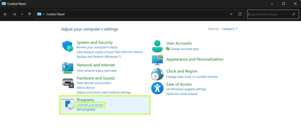
                        Download

                          Download

                            Download