Top Improvements to SOLIDWORKS Browser-Based Roles

BLOG

Top Improvements to SOLIDWORKS Browser-Based Roles

[techtips_featured_image_shortcode]

At the forefront of CAD innovation and engineering design quality of life, the 3DEXPERIENCE platform is constantly looking for ways to improve how the world’s engineers and product designers work. From improving their options for browser-based 3D modeling to adding new, more accessible tools and collaboration opportunities, the 3DEXPERIENCE platform adds new features as often as the world starts a new design! In this blog, we’ll discuss some of the most recent upgrades, improvements, and additions to the browser-based roles on the 3DEXPERIENCE platform to see how both designers and non-CAD users, worldwide, can benefit and enjoy a more accessible, more fluid daily design and product development routine. 


Without further ado, let’s dive into the R2023x FD02 release. 

1 . User Experience Quality-of-Life Upgrades 

New Default Dashboard

Now, you can access all your roles in one convenient location – the SOLIDWORKS Creator Home dashboard. This dashboard is designed to help keep you organized and reduce screen clutter, allowing you to quickly access your 3DEXPERIENCE roles. 

  • Get easy access to all your roles in one place. 


System Status Menu

Enhance system performance and accurately track issues with the new System Status menu. This menu allows you to easily check the status of your network and server connections, so you can quickly identify any underlying problems that may be impacting performance. 

  • Ensure a smooth connection and a successful design experience before you start any project. 


Design in the Context of HomeByMe in 3D Creator

You can now take advantage of 3D Creator’s parametric capabilities and test for fit, function, and aesthetics when bringing your HomeByMe designs into the environment. HomeByMe, a free home design and furnishings solution by Dassault Systèmes, allows you to measure, reference, and mate to geometry in one place, ensuring your design fits your specifications. Easily share your 3D Creator models back to the HomeByMe community. 

  • Design in a more realistic, life-like setting, and take advantage of parametric capabilities. 


Selective Save

With the Selective Save feature, you can improve your collaborative workflow by saving parts of an assembly without interruption. You can quickly identify which components are locked, deselect them, and save only the components that you are currently working on. This eliminates the need to ask someone to unlock a file.  

  • Work more efficiently and without interruption. 


Lock Status and Unlock Requests

With the latest tools, you can quickly and easily identify which elements are locked and by whom, and then instantly send unlock requests directly to the right people in real-time. No more waiting for someone to unlock a file.  

  • Collaborate seamlessly, knowing exactly which components are blocked and who to contact for immediate access. 


Sketch Pattern

The Sketch Pattern command now offers increased control and flexibility when creating patterns with the new Skip Instance checkbox. This is a helpful tool when you don’t want certain instances of the pattern to be created in overlapping or whole areas. With the Skip Instance feature, you can quickly add or remove instances from your pattern without disrupting the overall pattern. 

  • It’s now much easier to create the exact pattern you need for your design. 


Hide/Show Options in Measured Command

The Measure command now offers added control and time-saving features with the Hide/Show Options. These options allow you to quickly capture measurements related to internal and hidden components that are located behind other geometry, so you don’t have to leave the Measure command to get the measurements you need. 

  • With the Hide/Show Options, you can save time and have more control over your measurements. 


Volumetric Section View

By using Volumetric Section View, you can create a bounding box to divide your design into sections, allowing you to view the internal components without being distracted by additional elements. With this view, you can focus solely on the task at hand, giving you the ability to gain a better understanding of your design. 

  • Easily cut through the clutter and gain clarity in your designs. 


2 . Manufacturing Definitions 

Section Views

With a new 3D view type, you can easily create professional representations of internal features and dimensions for downstream communication. This makes it easier to define manufacturing information for internal component geometry. 

  • Capture design intent and internal details of complex components more clearly. 


Bent Leader Option

You can now customize how you display your drawings with the new bent leader option in Manufacturing Definition Creator. This feature allows you to create annotations with bent leaders that meet ASME and ISO standards for radius and diameter dimensions, giving you more control over the look of your drawings. 

  • Be confident that all your drawings are compliant with industry requirements. 


STEP A242 Export

You can now use 3DPlay to share, view, and mark up STEP A242 files for downstream communication and manufacturing. This format provides the industry-supported model-based definition (MBD) workflows. 

  • Export 3D annotations more efficiently. 


3 . Freeform Design 

Align Vertices Command

The Align Vertices command has been updated. Now, when using shift-select, the first two entities you select will define the alignment axis for all the remaining points. 

  • Specify vertices for alignment more easily. 


Bend and Flex Tool

When using the Flex tool, the robot manipulator and range manipulator are now offset from one another, making them easier to use. Additionally, the Bend tool now offers a Limit Bend option that allows you to ensure the deformation of a specific design region without bending the region beyond the manipulator. With this new option, you can easily control the exact shape and form of your design. 

  • Make your design intent clearer and gain increased control. 


Improved Copy/Paste

With improved Copy and Paste, placing a copied instance of a subdivision (Sub-D) body is easier than ever. When you Copy and Paste, a preview of the new instance appears in yellow, allowing you to accurately locate it in the desired position. You also have the option to scale and flip the instance. 

  • Create complex Sub-D geometry faster and more easily. 


Reflect Command

Creating a mirrored instance of an existing subdivision body is now even easier. Simply duplicate the existing body and use the mirror tool to flip the object along the desired axis. This will create a mirrored instance of the original body which can be modified independently of the original. 

  • Easily create a mirrored instance of a subdivision body. 


Crease Command

Save time with the new and improved Crease Command! When you apply a crease, the affected entities will remain selected, allowing for further modifications without having to reselect them. 

  • Save clicks and streamline crease creation. 


4 . Sheet Metal Design 

Enhanced Workflows and Mini Dialogs for Custom Walls

The Wall on Edge feature includes enhanced workflows and mini-dialogs that provide quick access to the sketch option and help to streamline the creation of custom walls and flanges. The workflow is shorter than before and the mini-dialogs are user-friendly, making it easier to use on smaller devices such as mobile phones and tablets. 

  • Create custom non-rectangular walls and flanges quickly and easily with the new Wall on Edge feature. 

5 . Structure Design 

Machine Learning for End Cap and Plate Placement

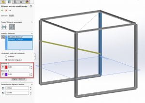
With the Design Assistant Selection capabilities, you will get suggestions for multiple end cap or plate placements. Simply click on one of the endcaps and the Design Assistant will automatically populate a suggestion for the other endcaps or plates and propagate them for you. 

  • Reduce time spent on manual work by quickly placing multiple end caps or plates. 


Find out more

Whether it’s communicating with colleagues or outside stakeholders, trying to add tools to a design more efficiently, encouraging experimentation with easy-to-use features, or just making your everyday designing more enjoyable, the 3DEXPEREINCE platform’s browser-based roles seek to make your daily design routines easier and more fluid, so you can focus on innovation. 


Watch this 3DEXPERIENCE presented video to see these enhancements in action:https://www.youtube.com/watch?v=JdBwc4Obc9Q


For more information or to request a 3DEXPEREINCE platform demo, contact the Xperts today!

X_green_halo

Any questions? Need help? Ask one of our experts.

Whether you’re ready to get started or just have a few more questions, you can contact us toll-free:

    Empowering 3D Journeys: Migrating to SOLIDWORKS, Implementing SWOOD, and Managing Change with Beaubois

    BLOG

    Empowering 3D Journeys: Migrating to SOLIDWORKS, Implementing SWOOD, and Managing Change with Beaubois

    [techtips_featured_image_shortcode]

    At SolidXperts, we pride ourselves on our proven ability to help our clients optimize their design and manufacturing processes through the use of modern software solutions. As a trusted SOLIDWORKS, 3DEXPERIENCE, and 3D design service provider with more than 25 years of experience, our Xpert teams enable our clients to design products faster and more efficiently, empowering them to stay competitive in ever-evolving industries.


    Recently, we’ve had the opportunity to work with Beaubois, a client in the architectural millwork industry, who was looking to transition from Solid Edge to SOLIDWORKS with the SWOOD add-on. In this post, we’ll share how we helped this client achieve their goals and improve their operations.


    Step 1: Complete Process Diagnosis


    Woodworking and architecture projects require a great deal of precision and expertise to create beautiful and long-lasting designs. To accomplish this, it’s important to use the right tools and software.

    As a Quebec-based company that specializes in custom architectural woodwork, Beaubois aims to push boundaries and challenge the expected norms of the woodworking industry without sacrificing high standards and quality designs. In order to keep up with their unique customer requests and an increasingly intricate digital design landscape, they needed to take their design processes to a higher level of CAD and CNC machine communication.


    To empower Beaubois’s 3D creative journey and support their long-term goals, our first step was to conduct a comprehensive diagnosis of our client’s existing design and manufacturing processes. We wanted to identify any inefficiencies or areas where improvements could be made. This process included an in-depth analysis of their CAD data, production workflows, and automation processes.


    Step 2: Pilot Project Implementation


    After the diagnosis phase, we moved to the pilot project implementation stage. We worked closely with a small team of Beaubois employees to test the SOLIDWORKS software and the SWOOD add-on in a real-world scenario. The pilot project allowed us to identify any potential issues and make necessary adjustments before a full-scale deployment.


    Moving from Solid Edge to SOLIDWORKS can be an intimidating prospect. Even with a perfect solution, it can be difficult to onboard a full team quickly and cost-effectively while avoiding expensive downtime. For Beaubois, SOLIDWORKS offers superior CAD collaboration capabilities and a more intuitive user interface, along with improved 2D and 3D functionality.


    Our team of Xperts helped onboard their design team to the SWOOD add-in, which provides a library of woodworking components, tools for designing 3D assemblies, the ability to create 3D renderings and presentations, and much more that allowed them to streamline their processes. The add-in also includes tools for estimating material costs and calculating production times, helping companies better manage their projects. With the SWOOD add-in, Beaubois can now design high-quality woodwork projects faster and more easily. Furthermore, SOLIDWORKS and SWOOD empower them to generate accurate and detailed toolpaths for their CNC machines.


    Step 3: Global Deployment and Change Management


    Following the successful pilot project, we helped the client roll out SOLIDWORKS with SWOOD across their entire organization. We provided extensive training and support to ensure a smooth transition and minimize any potential disruption to their operations. We also assisted with change management to help the client’s employees adapt to the new software and processes.


    As Beaubois transitioned to SOLIDWORKS and SWOOD, the investment in training and infrastructure was essential to ensure a successful transition and maximize the rewards of better design and fabrication processes.


    Step 4: Improved Results


    Our work with this client resulted in several key improvements to their design and manufacturing processes. With SOLIDWORKS and SWOOD, they were able to optimize their CAD data for use with their factory robots, leading to faster and more efficient production. Additionally, the SWOOD add-on allowed them to automate many of their manufacturing processes, further improving efficiency and reducing errors.


    Thanks to SolidXperts’ help, Beaubois has been able to transition to SWOOD for design and fabrication, resulting in enhanced communication and collaboration among staff, customers, and suppliers. This streamlining of the design process has saved Beaubois both time and money, while also allowing them to create products of the highest quality that exceed customer expectations. SolidXperts’ guidance and support during the transition enabled Beaubois to significantly increase their output and cost efficiency, while simultaneously creating more productive, more easily managed workflows.


    Conclusion


    We’re proud of the work we did with this client, and we believe it can serve as an inspiration to other businesses looking to improve their operations. To highlight our work, we created a video testimonial featuring the client discussing their experience working with us. In the video, they describe how our team helped them achieve their goals and improve their processes. Check it out!


    More info about Beaubois


    Explore all your SWOOD options on the official website here


    We are passionate about helping our clients achieve their goals through the use of modern software solutions. Our work with this client in the architectural millwork industry is a great example of how we can help businesses improve their operations and achieve success. If you’re interested in learning more about our services or how we can help you optimize your processes, please contact us today.


    Explore our services


    Contact the Xperts

    X_green_halo

    Any questions? Need help? Ask one of our experts.

    Whether you’re ready to get started or just have a few more questions, you can contact us toll-free:

      Using SOLIDWORKS Simulation for Precise Structural Finite Element Analysis

      BLOG

      Using SOLIDWORKS Simulation for Precise Structural Finite Element Analysis

      [techtips_featured_image_shortcode]

      Using the finite element analysis (FEA) tools available in SOLIDWORKS can help engineers, designers, and other professionals quickly and accurately analyze the performance of their 3D designs. FEA is a powerful toolkit for predicting the behavior of structural components and assemblies across a wide range of conditions. It can help to reduce the number of physical prototypes that must be produced before a design is finalized.


      To get started with your SOLIDWORKS tools, you’ll first need to understand the basics of FEA and how it can be used. FEA is a computational method that uses mathematical equations to simulate the behavior of a structure or component under different conditions. The equations are used to determine how the component or assembly will react to various forces and environmental factors such as temperature, vibration, and pressure.


      To begin, you must open the SOLIDWORKS Simulation application from the Tools menu. This will provide the user interface for setting up your FEA analysis.


      Picture3


      The first step is to define the type of analysis that you want to perform. You can choose from a variety of analysis types, such as linear static, non-linear static, modal, and fatigue. For each type of analysis, you’ll need to define the boundary conditions, loads, and material properties.


      Once you’ve defined the analysis type and boundary conditions, you can then set up the mesh. The mesh is a grid of elements that are used to model the behavior of the component. The number of elements and their size will depend on the accuracy that you need for your analysis. A higher number of smaller elements will result in a more accurate result but will take longer and more computing power to complete.


      Once the mesh is set up, you can then run the analysis. The results of the analysis can be visualized in the form of graphs, tables, and animations. These results can help you to quickly and accurately understand the behavior of your design under different conditions.


      Picture1


      Using the FEA tools available in SOLIDWORKS can be a powerful way to reduce the time and costs associated with prototyping and testing. By quickly and accurately analyzing the behavior of a design, you can reduce the number of physical prototypes that need to be produced and tested before a design is finalized.

      X_green_halo

      Any questions? Need help? Ask one of our experts.

      Whether you’re ready to get started or just have a few more questions, you can contact us toll-free:

        Taking Charge of the Next Wave of Product Development

        BLOG

        Taking Charge of the Next Wave of Product Development

        [techtips_featured_image_shortcode]

        Product development managers, directors, and vice presidents constantly make sure their teams are coordinated, and the products they design are cost-effectively manufactured, marketable, dependable, ergonomic, and useful.


        From initial design, all the way through to final manufacture, even a streamlined traditional product development process generates enormous volumes of data, frequently from several disconnected applications. Thousands of files, including parts, assemblies, drawing files, and files for simulation and manufacturing (OH MY!) may be found as integral pieces of a mechanical design project. Additionally, legacy files must be kept organized and accessible for efficient reuse. No one likes duplicating work. The management of everyday communication files, including spreadsheets, PDFs, and emails (among countless others), is also crucial, now more so than ever before.


        How can this data be promptly and efficiently captured, managed, and used for your company’s advantage?


        For those in charge of product development, finding and keeping the proper personnel has grown to be a constant worry. Nowadays, location is rarely a deciding factor in hiring, so allowing flexibility in terms of location has become critical as companies look for new ways to attract, retain, and motivate workers. The top talent seeks employment with cutting-edge businesses. Additionally, staff members who are given the freedom to reach their full potential and continually advance their abilities are happier and less inclined to walk away from a position.


        The comprehensive corporate innovation portfolio, 3DEXPERIENCE Works, links all your people, data, and apps in a single environment, allowing all important stakeholders to take part in the creation of new products. It makes use of the 3DEXPERIENCE platform on the cloud and combines the strength of SOLIDWORKS with other top-tier technologies from Dassault Systèmes.


        How can 3DEXPERIENCE Works help product development leaders as we enter the new generation of product design and development?


        Makes Decisions More Efficient

        The communication process between design/engineering teams and non-technical stakeholders, who frequently occupy executive-level decision-making positions, has always been difficult to maintain. To provide critical input and provide the go-ahead for initiatives, these stakeholders must fully comprehend product concepts. Without a clear grasp of engineering’s goal, tensions can easily rise, sometimes leading to communication breakdowns and painfully delaying the decision-making or even final manufacturing and market delivery processes.


        Using the 3DEXPERIENCE platform’s cloud-based collaboration capabilities gives non-engineering decision-makers a clear, concise, and curated window into that design process. Team members can explore models on the cloud-based platform at their own pace, regardless of their level of technical expertise. It enables people to take part in real-time reviews without needing to have the necessary 3D CAD skills.


        Collaboration and productivity on the front end soar when non-technical owners, executives, and managers are given early access to the design review process. Decisions are made more quickly, with wider spread agreement. It is simpler to express worries, find problems, and provide remedies. Potential problems are identified early in the procedure, preventing delays later on in the process.


        *Permission-based access may be granted to suppliers and clients so they can contribute to the security product record.


        Manages Data More Efficiently

        A few of the everyday issues encountered by product development executives and their teams include knowing who is working on what projects, when each phase of a project is due, why delays occur, and how to handle all the data.


        The portfolio from 3DEXPERIENCE Works was created specifically to control the product development life cycle. Teams may offer their departmental knowledge at key points throughout the process thanks to simple-to-use applications. Everyone may easily obtain status updates via a dashboard view since the tools are interconnected.


        This is fantastic news for SOLIDWORKS customers and other small-to-medium sized enterprises who lack the resources to set up a sophisticated data management system. Say goodbye to data extractions, screenshots, emails, Excel spreadsheets, and a jumble of other departmental tools thanks to 3DEXPERIENCE Works solutions. To reduce mistakes and communication blunders, the platform automatically maintains an audit trail of both engineering and communications data.


        Data management for product development is increasingly favored using cloud-based PLM technologies. Smaller businesses can scale as their firm expands and invest only in the technologies they actually need. At its foundation, 3DEXPERIENCE Works has just one product definition.


        *Depending on their role and access privileges, everybody within the firm may see, change, and contribute to one continuous process.


        Ensures Collaboration

        Small-to-medium sized firms still frequently use phone calls, emails, and even, occasionally, faxes as their main methods of client communication. However, manufacturing utilizing the 3DEXPERIENCE platform is automatically in-sync with product development. Regardless of whether things are made in-house or by other parties.


        Lack of coordination can reduce production and raise the cost of the final product. With the aid of the tools provided by a cloud-based platform, you can establish project Communities where you can invite everyone involved, including clients and suppliers, to work more securely and efficiently.


        Upstream issues that might be costly are avoided by using real-time design for manufacturing input from the shop floor or suppliers. Additionally, the platform records every conversation, making it possible to backtrack activities.


        *Late-stage product difficulties are eliminated when designers and engineers are involved in manufacturing early in the process.


        Everyone Moves in Unison

        Utilizing each member of your team’s area of expertise is made simpler by the design-through-manufacturing solutions portfolio offered by 3DEXPERIENCE Works. On the platform, basic data management is already integrated, and if your business develops and your needs change, you can add or change your features and roles. Additionally, you have access to technologies created specifically for product development that are accessible to all important stakeholders, including executives, design engineers, shop floor workers, and suppliers.


        For more information about the 3DEXPERIENCE Works portfolio, or to see how you would benefit from a secure and easy shift to cloud-based PDM or PLM workflows, don’t hesitate to reach out to our Xperts.


        X_green_halo

        Any questions? Need help? Ask one of our experts.

        Whether you’re ready to get started or just have a few more questions, you can contact us toll-free:

          3DEXPERIENCE SOLIDWORKS 2023 WHAT’S NEW

          BLOG

          3DEXPERIENCE SOLIDWORKS 2023 WHAT’S NEW

          [techtips_featured_image_shortcode]

          ASSEMBLIES

          Optimization of lightweight / resolved :

          Lightweight supports part mass and similar properties.

          Auto repair of mate references

          Improved assembly cut feature

          Highlighting for overwritten BOM cells

          Specify the default BOM part number (as either Document or Configuration name)

          Improved STEP export

          Preview of Replace Component with instance(s) to replace controls

          Color option for Explode Lines

          Specify affected configuration(s) for skipped instances in patterns.

          Ability to suppress magnet mates & related connection points

          Override computed mass or cg values with Design Table entries

          Assembly feature propagation blocked from affecting Toolbox parts

          Assembly patterns with skipped instances are easier to configure.

          Replace component improvement, better options for instances, and more.


          COMPOSER

          View Collections capability

          Updated import file format support

          Support of Pro/E, CREO & STEP meta properties


          DRAWINGS

          Component Name display choices made in part or assembly feature tree are reflected in the Drawing view pallet.

          Detached Drawings are fully discontinued and replaced with Detailing Mode

          Detail drawings of assembly components can be opened directly from the assembly drawing without opening respective geometry files.

          RMB graphics area, BOM cell, or drawing view tree.

          Not fully supported for Detailing Mode.

          BOM table overrides can now have a specific highlight color. (default Sys Opt is black)

          RMB selection is provided to restore to original values per cell, row, column, or the entire table.

          Highlight color only shows when the table is selected. (not for print and so on)

          Quantity indicators now allowed for Auto Balloons as well as manual balloons.

          BOM tables can now be filtered like a spreadsheet, and the auto balloons update to match.

          Do not combine filtering with the hiding of columns or rows.

          Transparent component support for HLR / HLV views improved to match with ISO standard 128-2020.

          Check box option in view PM or in Document Properties.

          Hole Tables now support punches and slots in addition to holes (a top 10 ER).

          GeoTol symbols can be limited to the current drawing standard.

          Vector translation modifier now supported in GeoTol frames.

          Dynamic Profile Tolerance supported per ASME Y14.5-2018


          EDRAWINGS

          Assembly display and publish improvement

          Model Configuration support for eDrawings mobile apps

          Publish support for Display States in eDrawings

          Display Style improvements

          File type version enhancement

          Multi-language support for eDrawings to web HTML

          Inch fractional measurement units


          ELECTRICAL

          Support for hybrid drawings – schematics & tables combined on 1 sheet

          Component dynamic connection label annotations supported in schematics

          Ability to set 3D part mass props from Electrical Schematic properties (per spec sheet)

          Improved condition icons for 3D electrical components (inserted, connected, and so on)

          Open ended wire support in schematic. (for pigtails or wire on install connections)

          Schematic sheets support more image types. (tiff, png, jpg)

          Deleting Component can force deletion of related symbols

          Reset for Dismissed Messages

          Excel Automation Improvement

          Origin -> Destination specification


          FLOW

          Mesh Boolean Operation – allows meshes to create even when base geometry is imperfect

          Turbidity Factor – for solar radiation effects, accounts for polluted or storm-filled atmosphere

          Reduces heat effects in some cities versus open desert

          Plot Cropping – (cut, mesh, surface) restrict the display to a particular material or fluid domain

          Tangential & Radial Velocity effects for Fan Curves – property allows a more thorough definition of fan performance

          Heat conductance on porous media as dependent on specific mass flow – increases accuracy for compressible fluid and gas flows.

          Project Tree Sorting – alphabetically or chronologically

          Transient Explorer export options – export results by time range, or for the active time moment

          Transient Explorer custom parameters – for better visualization

          New Study Goals –

          Total Energy Balance

          Volumetric Heat Generation Rate

          Radial & Axial Velocities

          Flux Plots with total energy balance display

          Performance – Mesher and Solver operations are now faster due to improved memory use management


          IMPORT/EXPORT

          Large assembly export supports individual STEP file generation

          Textured *.obj file import is improved


          INSPECTION

          AddIn – Balloon Sequence configurability

          With multi-sheet options

          Addin – Balloon Drawing Sheets Separately

          Addin – Export sheets as separate PDF files

          Addin – Export reports as separate Excel files

          Addin – Inspection Manager with Characteristic tree view

          Standalone – Autoballoons for PDF drawings

          Standalone – Manual Extract replacement for OCR (better results)

          Machine Learning support for 2D PDF

          Sheet selection mode for multi-sheet drawings

          Export Reports to individual Excel files

          Balloon Sequencing


          INSTALLATION & SNL

          Flow Simulation HVAC and Electronics Cooling modules can now be independent AddIns and the SNL licenses loaded or unloaded as needed rather than always being reserved with each use of Flow Simulation.

          Term licenses now show pending expiration in the SNL manager and can be renewed or reactivated by individual serial numbers.

          All products will now have a term license option.


          MANAGE

          Automatic update of mapped linked records

          New From option for data fields

          BOM field comparison (linked vs primary)

          Variable Driven BOM Qty support

          Cancelled Tasks reflect properly in capacity planning

          Task Board Display


          MBD

          View control for all dimension types, not just DimXpert annotations

          Hole Tables support multiple views

          Dimension Extension Line

          Datum Feature editing

          Wedge as geometric & annotation feature

          Support for ISO Tolerance modifiers


          PART MODELING

          Support of Move/Copy Body translation or rotation values in Equations and Design Tables

          Defeature now supports creating derived configurations for parts as well as assemblies.

          Dimension support in Move/Copy Body

          Allowance of Library Feature Errors – click [Yes] to accept the feature errors, and then correct them after the insertion in the current part.

          Coordinate Systems are now valid for selection in more commands – such as, 3D sketch operations, 2D sketch dimensions, mirror, and during select other

          Single stroke font support in Wrap Feature sketches (Scribe wrap type)

          OLFSimpleSans – is installed by SOLIDWORKS

          Hybrid Mesh-BREP modeling improvements

          Extended feature support

          Section View creation through Axis

          Euler method rotation is now allowed for Move/Copy Body, and it can be set per configuration.

          Move/Copy Body translations can also be set per part configuration now.

          Global variables or equations can now be used to drive the Move/Copy Body values.


          PDM

          HTML customization for Notification templates

          File Version Upgrade Tool – supports overwriting latest version

          Streamlined UI for check-in/out

          New options to manage Deleted Users

          Transition Actions configurable by user account and properties thereof

          Tooltips can be added to Data Card fields

          Improved Data Card controls

          Copy & Paste display text to variable fields

          Buttons can have user-lookup data (names, AD fields, and so on)

          Better image file support. (jpg, png)

          Logging of File Retrieval Operations ([x]Get log property at PDM Pro server)

          Display source Groups for Inherited User Permissions

          All data transfers encrypted to/from the server

          STEP export task enhanced for 242, or shattered assembly components.

          eDrawing files in the vault support thumbnail previews in the explorer panel.

          Autologin option for vault Admin. (setting in the admin tool at a local machine)

          Archive Server & Database Server improved in higher latency environments (Azure, AWS)

          Private State folder visibility option for non-Admin users.


          PERFORMANCE

          Level of Detail system option to improve graphics changes (zoom, pan, rotate) for most view types.

          Faster save operations for large assemblies with some amount of unchanged components.

          PDM is faster and more efficient in high-latency networks.

          PDM file version upgrade tool operates faster.


          PLASTICS

          Material Database & Material Grade additions

          Material Database UI improvement

          Report enhancements


          ROUTING

          Improved electrical flattening and manufacturing drawings

          With better connector tables.

          Multi-wire circuit splice support.

          Design Library auto-style clips added.

          Routing Library Manager performance and usability improvements.

          Harness diameter & length are show in an electrical route property manager.

          Accommodates and displays unused cores.

          Auto Route improvement for discrete wires


          SHEET METAL

          Deviation sensor

          You can create a sensor to alert that the sheet metal exceeds a bounding box size. (max length, width, area, blank area)

          Symmetrical Thickness

          Specifies material to be applied symmetrically from the base flange sketch.

          Gauge Values in Cut List properties (and drawing notes)


          SIMULATION

          Improved surface to surface bonding interactions (allowed for non-contacting faces)

          For ignoring set screws, pins, etc.

          Diagnostic Tools

          Linkage Rod Connector

          Penalty Stiffness Control for Contact (up to 50% solve)

          Solver improvements

          Underconstrained Body management (Simulation Professional & Premium)


          SKETCHING

          Elipses now have options to create construction lines across the axes.


          SOLIDWORKS CAM

          Barrel Tool Support

          Improved Leadin & Leadout Calcuation for contour milling

          Lines Only Option for VoluMill Toolpath

          Tolerance Based Machining improvements


          STABILITY

          90% reduction in customer reported crash SPRs.STRUCTURE SYSTEMS

          Corner Trims of similar corners by Group, with Connection Plates by Group

          Configuration specific weldment member sizes

          Alignment of Custom Properties Attributes (for matching with 3DEXPERIENCE attribute types)


          USER INTERFACE

          Comments in SOLIDWORKS files now have additional color and formatting options.

          Comments can be set to Show At Start when files are opened.

          Improved Restore Default Settings options and behavior.

          Improved behavior of Copy Options Wizard.


          VISUALIZE

          Color Picker tool improvements

          DSPBR Materials Support

          Import Options (grouping) are easier for SOLIDWORKS files

          Stellar Physically Correct illumination render

          PhotoView 360 to be retired at 2023 sp5.

          X_green_halo

          Any questions? Need help? Ask one of our experts.

          Whether you’re ready to get started or just have a few more questions, you can contact us toll-free:

            This Year’s Top 10 Enhancements in SOLIDWORKS Browser-Based Roles

            BLOG

            This Year’s Top 10 Enhancements in SOLIDWORKS Browser-Based Roles 

            [techtips_featured_image_shortcode]

            SOLIDWORKS browser-based roles are purpose-built for your needs and include parametric modeling, subdivision (Sub-D) modeling, and much more, and since they run on the 3DEXPERIENCE platform you also get built-in data management and collaboration capabilities that benefit the whole team. The latest enhancements brought in with SOLIDWORKS 2023 for these solutions include 2D drawing improvements, smart mates, and net surfacing, as well as improvements to downstream communication for manufacturing to help you be as productive as possible. 


            Let’s have a look at this year’s top 10 enhancements. 


            1- 2D Drawings | Manufacturing Definition Creator – Create both 3D definitions and 2D drawings to meet supplier requirements faster. 


            Manufacturing Definition Creator easily creates both 3D product manufacturing information (PMI) and 2D drawings. Use either model-based definition (MBD) or 2D sketches to break down the barrier between 3D and 2D and leverage model-based workflows while providing the flexibility needed to preserve existing manufacturing processes and supplier relationships that still use 2D drawings. 


            With Manufacturing Definition Creator, you don’t have to create a 2D drawing from scratch, you can use your existing 3D PMI to create a 2D drawing complete with definition, in a matter of a few mouse clicks. 

            blog-img

            Manufacturing Definition Creator features 3D definition and 2D drawing capabilities. 


            2- Welcome App | 3D Creator – Get up to speed on your new solutions quicker with a personalized welcome experience. 


            Whether you’re a new or experienced user, the Welcome app in the 3D Creator parametric design role helps you get up to speed, fast. Access the SOLIDWORKS online communities, switch seamlessly between your roles, and explore the Learning Center where you’ll find tips for getting started, in-depth learning tutorials, and Sample Content. Drag and drop a model into your interface to check out the role’s modeling features. 


            In addition to launching your roles, you can open your collaboration and management apps: 3DPlay, the Bookmark Editor, and more. 

            blog-img

            Access key role and app information plus SOLIDWORKS online communities directly in the Welcome app. 


            3- Design Assistant Smart Mate with Artificial Intelligence (AI) | 3D Creator – Build assemblies faster. 


            Design Assistant Smart Mate is one of the many AI-enabled features that uses built-in machine learning algorithms to offer design guidance based on your workflows. This tool is designed to help you create mates by dragging and holding a component in the position where you want it to mate with the surrounding components. The Smart Mate command will automatically launch when you drag a component close to the edge of another component.

            blog-img

            Drag and snap components into place with the Smart Mate command. 


            4- Net Surfacing | 3D Sculptor – Create subdivision surfaces using familiar CAD operations. 


            Create your own primitives using a loft, a boundary condition, or a sweep with the Net Surfacing Command in the 3D Sculptor Sub-D modeling role. Start by defining a surface using familiar parametric commands, then use freeform Sub-D modeling to modify the shape of your customized primitive. You can also toggle between the customized parametric surface or subdivision surface. To increase design efficiency, choose pre-defined primitives or create your own with the Net Surface command. 

            blog-img

            Use familiar CAD operations to create a subdivision surface with Net Surfacing in 3D Sculptor. 


            5- 3D Print Orientation and Nesting Optimization | 3D Creator – Automatically set your parts up for success and save time on 3D prints. 


            The Print3D feature gives you the option to auto-arrange a selection of parts on the 3D printer build plate. Work smart and let the Print3D feature work hard for you to get the most efficient layout of your assemblies. This feature also helps reduce material costs! 

            blog-img

            Create the most efficient layout with automatic optimization and nesting and reduce material costs. 


            6- OM Tables | Manufacturing Definition Creator – Clearly define your assemblies and provide critical assembly information. 


            Easily and efficiently provide the most valuable information with 3D definitions and 2D drawings. Create and include a bill of materials (BOM), and automatically link BOM table values directly with ENOVIA for consistent, up-to-date information. 


            Customize your BOM tables using familiar table editing functionality and provide a wide range of linked assembly properties, such as part quantities, revisions, part numbers, and more. 

            blog-img

            Create a detailed bill of material (BOM) tables for 3D assembly definition and 2D drawings. 


            7- Automatic Corner Trimming | 3D Structure Creator – Save time by automating corner trimming processes.   


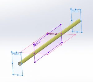
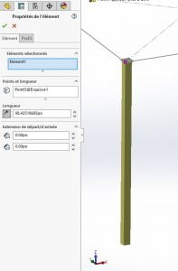
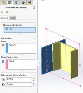
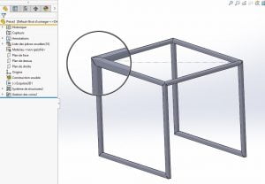
            Create accurate, manufacturing-ready structure designs, and do it quickly with 3D Structure Creator. The Automatic Corner Trims feature enables you to automatically trim members during member creation, so you don’t have to do this after. Create members based on sketch segments, model edges, points, or intersection planes, or between two members, and check Enable Automatic Corner Trims to trim corners and endpoints. 

            blog-img

            Create structure systems faster by automatically trimming members during member creation with 3D Structure Creator. 


            8- Recognize Command | 3D SheetMetal Creator – Increase productivity and create complex sheet metal shapes using traditional modeling features. 


            3D SheetMetal Creator features easy-to-use associative parametric sheet metal design tools. The Recognize command, for instance, includes solid and surface options so you can easily create complex sheet metal shapes and reduce complex design workflows. In addition to the “thin” option, you can convert solid bodies and surfaces with automatically generated flat patterns for manufacturing that doesn’t require shelled or uniform thickness geometry. 


            You can also customize bends, walls, splits, and gap distances with a single command! 

            blog-img

            Create complex sheet metal geometry using conventional convert-to-sheet metal workflows in 3D SheetMetal Creator. 


            9- Selection Accelerators | 3D Sculptor – Speed up selections and easily shape sub-D mesh. 


            There are several new selection accelerators you can access from the context toolbar and by using Shift Select. If you need to select a group of tangent edges or faces, you can use the Select Tangency accelerator on the context toolbar. 


            To select edges around the face of a box or quad ball, there’s a Corner Loop accelerator that lets you Shift Select two edges on either side of a corner to select the entire loop, and for creased edges, you can use the Select Crease accelerator on the context toolbar so you can select connected creased edges. Also, shift select will follow along creased edges. 

            blog-img

            Speed up geometry selection and modifications using new selection accelerators in 3D Sculptor. 


            10- Thickness Analysis | 3D Mold Creator – Ensure uniform thickness and improve design integrity by verifying that parts will fill properly. 


            3D Mold Creator provides specialized mold tooling design functionality that enables the faster, automated, and more robust design of mold cores, cavities, and inserts. The Thickness Check tool, for instance, enables you to perform thickness checks using a rolling ball “sphere” method or the normal distance “ray” method. You can easily identify thickness ranges using colors, in addition, to manually investigating thicknesses at specific locations by clicking on the area you’d like to investigate. 

            blog-img

            Prevent sink marks by ensuring uniform thickness with the Thickness Check tool in 3D Mold Creator. 


            SOLIDWORKS browser-based roles available on the 3DEXPERIENCE platform enable engineers and designers to work more efficiently on designs and assemblies from anywhere in the world. With the release of SOLIDWORKS 2023 hundreds of improvements have been made to accelerate your 3D product design processes. For more information on all the improvements, and to know more about what SOLIDWORKS or 3DEPXERIENCE solutions best fit your workflows, don’t hesitate to contact our Xperts teams

            X_green_halo

            Any questions? Need help? Ask one of our experts.

            Whether you’re ready to get started or just have a few more questions, you can contact us toll-free:

              How 3DExperience will help you use SOLIDWORKS  

              BLOG

              How 3DExperience will help you use SOLIDWORKS

              [techtips_featured_image_shortcode]

              By Steven Murphy – Elite Applications Engineer

              While the 3DExperience platform takes the CAD industry by storm, what does it mean for the average SOLIDWORKS user? Despite the industry trend toward SAAS (Software as a service), SOLIDWORKS will remain available as a perpetual license. The only change for conventional SOLIDWORKS users is access to a wider variety of tools using the 3DExperience platform to augment your current workflows. Knowing what tools you have access to on the cloud will give you a competitive edge and the tools you need to stay successful.


              Top Tools to Leverage 3DExperience Using SOLIDWORKS


              ENOVIAWORKS (PLM)

              Everyone is familiar with “the cloud,” or the idea of connecting via internet to servers remotely in order to gain flexibility and save on hardware costs. With the integration of ENOVIAWORKS into the 3DExperience platform, cloud PLM [Product Lifecycle Management] services are readily available to use with SOLIDWORKS files. This includes a complete product data management (PDM) system as well as tools to manage the processes surrounding the part’s fabrication.

              For the average SOLIDWORKS user, this means access to revision controlled files from anywhere you can use SOLIDWORKS. Just login to the PLM services pain integrated with SOLIDWORKS and you are off to the races. You can also drag and drop files from the 3DExperience platform into SOLIDWORKS to open and start working. On top of this functionality, the files in PLM can be referenced in chats, integrated into blog posts, and worked with in the 3DExperience “X Apps.” These X Apps provide a range of versatility for part creation without ever leaving the cloud.


              3DEXPERIENCE PLM SERVICES SOLIDWORKS View


              XShape

              XShape is the premier SubD cloud application available on the 3DExperience platform. Many industrial designers know the challenge of replicating complex surfaces inside of any CAD package. XShape allows for the creations of surfaces and parts using push-pull manipulation of primitive shapes while maintaining continuity. This functionality greatly surpasses the ability of SOLIDWORKS Freeform to create your aesthetically pleasing complex surfaces with your CAD file. On top of that, the SOLIDWORKS integration means that you can drag and drop the files from your web browser right into your model.

              If you are doing any surfacing, industrial design, or non- parametric modeling, this application is a must have. Because this application was developed with SOLIDWORKS in mind, the seamless transition between software will support your workflow.


              XShape SubD Modeling


              3DExperience Marketplace

              Who knew that you have access to quality industrial suppliers worldwide within SOLIDWORKS itself? You can find the manufacturers that your product needs without having to spend time and effort creating your own supply chain. This especially powerful in an industry where rapid prototyped 3D printed parts are becoming the de facto standard. Directly integrated with your SOLIDWORKS model, you can get competitive pricing, see shipment costs, and determine which provider meets your deadline.


              The 3DExperience Marketplace is located in the “3DExperience Platform” add in located in SOLIDWORKS which provides the flexibility that any engineer can take advantage of. Let Dassault Systèmes qualify the manufacturers for you, all you need to do is provide the model!


              3DExperience Marketplace Within the Task Pane


              The 3DExperience brings value to all conventional SOLIDWORKS users, expanding the tools available to bolster your workflow. The platform provides you with the ability to create new types of models, store and access data online, as well as easily identify manufacturers based on your requirements. From here, the Dassault Systèmes ecosystem will only continue to adapt and grow.


              Interested in the 3DExperience Platform? Reach out to our Xperts anytime with any questions or for more information.

              X_green_halo

              Any questions? Need help? Ask one of our experts.

              Whether you’re ready to get started or just have a few more questions, you can contact us toll-free:

                How to add the Thickness of Sheet-metal as gauge in a Layout

                BLOG

                How to add the Thickness of Sheet-metal as gauge in a Layout

                [techtips_featured_image_shortcode]

                In this tech tips we are going to find out how to add the Thickness of Sheet-metal as a gauge in a Layout:

                When one designs products with sheet metal, the industry uses the thickness values from a gauge table. For example, an 18 gauge is equivalent to a thickness of 0.0359 for a steel part. It is possible to use this kind of table in the sheet-metal function of Solidworks.

                Continue reading “How to add the Thickness of Sheet-metal as gauge in a Layout”

                Enhancements in PropertyManager in SOLIDWORKS Simulation

                BLOG

                Enhancements in Remote Loads/Mass PropertyManager in SOLIDWORKS Simulation

                [techtips_featured_image_shortcode]

                By Sakineh Orangi – Simulation Application Engineer at SolidXperts

                In SOLIDWORKS 2019, the Remote Load/Mass PropertyManager was redesigned to improve the user experience and it introduced distributed coupling. The Remote Loads/Mass PropertyManager allows us to apply remote loads, remote masses, and remote displacements for static, topology, and nonlinear studies. One of the ways to access the Remote Loads/Mass PropertyManager is to right-click on External Loads in the simulation tree of linear static, nonlinear static, or topology.


                We select the faces to apply remote loads, remote masses, or remote translations and/or rotations.


                We define the coordinate system used for the interpretation of the location and directions of the remote features.


                After this step, we enter the coordinates of the reference node location in a local or global coordinate system.


                In the case of the definition of remote force or remote distance, we check the Translational Components and enter the values of remote loads or remote translation in the three directions X, Y, and Z.


                If there are any remote moments or remote rotations, we check Rotational Components and then enter the data.


                 data-lazy-src=


                Learn more about everything new in SOLIDWORKS from 2015 to 2019 by downloading our White Paper.

                To learn more about SOLIDWORKS Simulation, click here.
                X_green_halo

                Any questions? Need help? Ask one of our experts.

                Whether you’re ready to get started or just have a few more questions, you can contact us toll-free:

                  Better integration of SOLIDWORKS Electrical for SOLIDWORKS PDM

                  BLOG

                  Did you know that a better integration of SOLIDWORKS Electrical for SOLIDWORKS PDM is now available?

                  [techtips_featured_image_shortcode]

                  SOLIDWORKS provides you with a new tool: SOLIDWORKS Electrical integration for Professional SOLIDWORKS PDM 2018. SOLIDWORKS Electrical Integration for SOLIDWORKS PDM is a new SOLIDWORKS Electrical component that implements a better integration with SOLIDWORKS PDM Professional.

                  SOLIDWORKS Electrical Integration for SOLIDWORKS PDM is a free product that will be available to customers using SOLIDWORKS Electrical 2D and SOLIDWORKS PDM Professional.

                  SOLIDWORKS Electrical Integration for SOLIDWORKS PDM is being released with SOLIDWORKS Electrical 2018
                  The most important functionalities of this tool are:

                  • SOLIDWORKS Electrical users will obviously be able to store their projects in SOLIDWORKS PDM from within SOLIDWORKS Electrical.
                  • Allow the work-sharing between users.
                  • Variable mapping between both products so that key electrical metadata can be made available in SOLIDWORKS PDM.
                  • Electrical components libraries will be pushed and synchronized to SOLIDWORKS PDM
                  • “Where Used” information will be available.
                  • This product will also manage electrical deliverable files, such as PDF and DWG.
                  • It will also publish an advanced electrical Bill of Material (BOM) to SOLIDWORKS PDM.

                  Installation, administration and users guide will be installed in the installation folder of SOLIDWORKS Electrical integration for Professional SOLIDWORKS PDM 2018.

                  Once SOLIDWORKS Electrical integration for Professional SOLIDWORKS PDM 2018 was installed in SW Electrical, you must define some parameters in the administration of the tool.


                  You will beforehand have created a folder structure in your PDM vault to host your 2D SW Electrical projects, and logs, as well as a Library folder for synchronization of SW Electrical.

                  In the tab General Settings:
                  Choose your Vault and the library folder in your vault.

                  In the tab Log Settings:
                  Define the folder of logs inside the vault, as well as its options.

                  In the tab File Structure:
                  According to SOLIDWORKS Electrical document types, you can make some Mapping.

                  To start the collaboration of SOLIDWORKS Electrical integration and SWPDM.
                  Since you are Project Manager:
                  Unarchive and open your SW Electrical project
                  (Files *.tewzip)

                  Work on your project as usual, when ended.
                  Make a synchronization of your library towards PDM,
                  by using Synchronize Libraries.

                  And make Check-in:

                  As asked, select the parent file of your project.

                  A table showing all the files which will be archived will appear, click Add.

                  Let the process make the creation of all the objects of your project (it can take some time).

                  Once the process is completed; you will notice that the structure of your project SOLIDWORKS Electrical was duplicated in PDM. by adding a folder BOMS.
                  and creating a .pdf file of your complete drawing package.

                  SOLIDWORKS Electrical

                  Local PDM view

                  SOLIDWORKS Electrical


                  Local PDM view

                  You will also notice the creation of all your drawings in .dwg format.

                  All the PDM tabs will be accessible. You can even design a specific card for your SOLIDWORKS Electrical projects.

                  As well as file cards which will inherit some properties of their folder card.

                  In the folder BOMS; you will find all the bills of material for your project. It will be possible for you to open and export your BOM throw Excel such as any other BOM in PDM.

                  By choosing a file of a BOM (Click + right button of the mouse) to obtain the options such as: Browse to, allowing to go to the localization of the library parts.

                  This new tool will allow better collaboration between your electric and mechanical engineering departments. If you have any questions just contact one of our Xperts.

                  On the same subject, take a look at the video produced by SOLIDWORKS:

                  X_green_halo

                  Any questions? Need help? Ask one of our experts.

                  Whether you’re ready to get started or just have a few more questions, you can contact us toll-free:

                      Download

                        Download

                          Download