A Beginner’s Guide to SOLIDWORKS

BLOG

A Beginner’s Guide to SOLIDWORKS

[techtips_featured_image_shortcode]

Steven Murphy – Certified SOLIDWORKS Expert (CSWE)

So you want to learn SOLIDWORKS? Well, you are in luck- SolidXperts has your back! Whether you are learning SOLIDWORKS as your first Computer-Aided Design (CAD) package or augmenting your software portfolio, this guide will go through the information you need to get you up and running in no time!

Step 1: Know your Resources

Good News: you are not the first person to learn the software! SolidXperts is helping people just like you to learn the software on a daily. The SOLIDWORKS community can also provide a ton of valuable material to augment your learning experience. Here is a list of the resources that you should become familiar with:

In-Person or Online Training

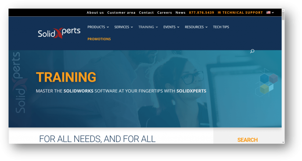
The most important resource for getting up to speed quickly on SOLIDWORKS is the online and in-person training courses provided by SolidXperts. These classes are designed to teach new users not only how to use SOLIDWORKS, but to understand the thought process behind design intent. You will work with SOLIDWORKS Experts who will personally cater to your learning style.  The “SOLIDWORKS ESSENTIALS” class is the best way to get to where you want to be.
Tutorials

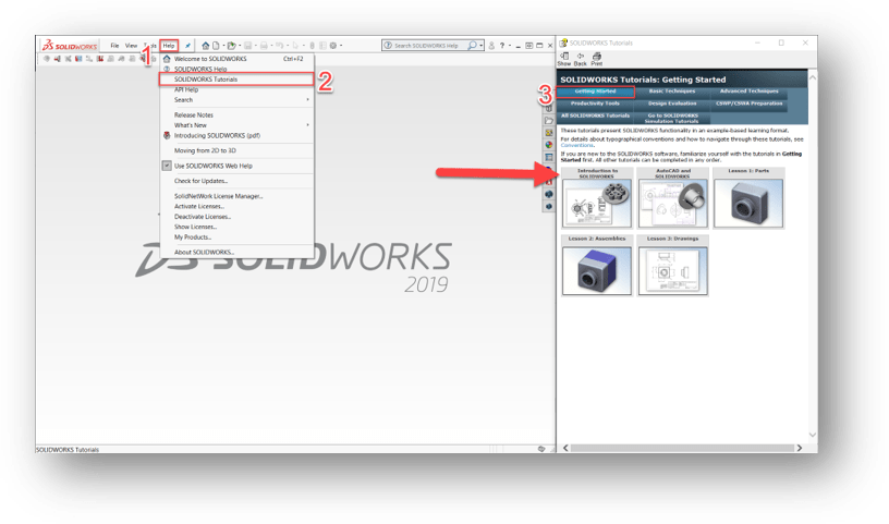
Did you know that SOLIDWORKS has built-in Tutorials to teach you the software? Located under Help (1)> SOLIDWORKS Tutorials (2) > Getting Started (3), there are a series of hands-on tutorials that will walk you through learning the basics of the program.
Blogs & Forums

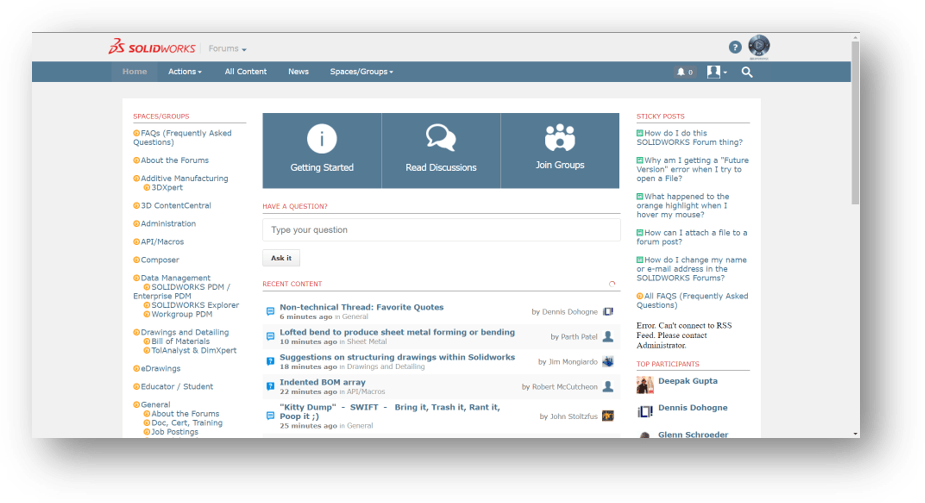
Well, you already found this blog, so you are on the right track! From walkthroughs to tutorial videos to Q&A threads, the SOLIDWORKS community is here to help you succeed. No matter your skill level, there is tons of value to be gained from interacting with other users who have the same questions as you!
My.Solidworks.com

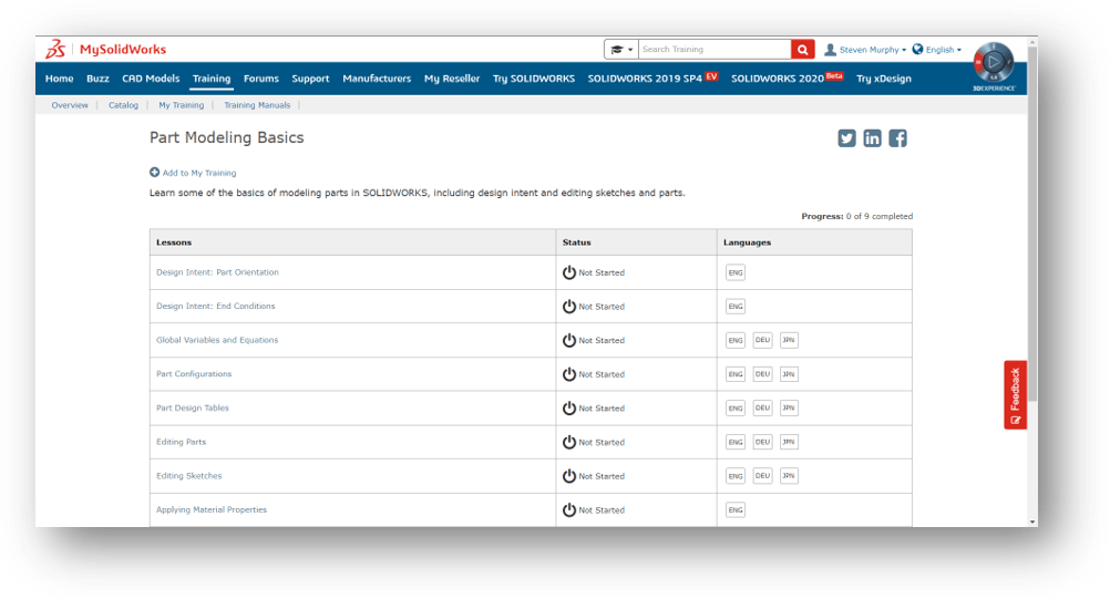
Provided by SOLIDWORKS, MySolidworks contains many training paths (each training path is composed of many individual topic videos) targeting a specific workflow of the software. Use these to your advantage to learn about areas of the software that is relevant to your profession. I would suggest starting with the “Part Modeling Basics” learning path.

*Note: online training works best when it is used to augment in-person training! Good modeling habits developed in the classroom have more staying power and will serve you better in learning the software.
Step 2: Learn the User Interface

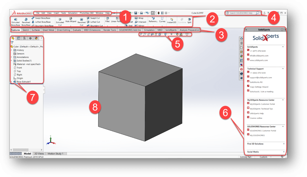
A key portion of getting used to any new software is learning the user interface (UI). You want to be comfortable navigating through the menus. Here is a brief description of the key UI elements for getting started:

  1. Menu Bar

The Menu Bar contains a set of the most frequently used tool buttons from the Standard toolbar, the SOLIDWORKS menus, the SOLIDWORKS Search, and a flyout menu of Help options.

  1. CommandManager

The CommandManager is a context-sensitive toolbar that dynamically updates based on the toolbar you want to access. By default, it has toolbars embedded in it based on the document type.

  1. CommandManager Tabs

When you click a tab below the CommandManager, it updates to show that toolbar. For example, if you click the Sketches tab, the Sketch toolbar appears.

  1. SOLIDWORKS Search

You can use SOLIDWORKS Search to find information in documentation and forums. You can also find files and models, and find and run a SOLIDWORKS command with just a few keystrokes.

  1. Heads-Up Toolbar

A transparent toolbar in each viewport provides all the common tools required for manipulating the view.

  1. Task Pane

The Task Pane provides access to SOLIDWORKS resources, libraries of reusable design elements, views to drag onto drawing sheets, and other useful items and information. The SolidXperts custom task pane (part of UtilsXperts) has all of our contact information, tools, and custom macros to help our customer base take full advantage of the SOLIDWORKS software.

  1. Feature Manager Design Tree

The FeatureManager design tree on the left side of the SOLIDWORKS window provides an outline view of the active part, assembly, or drawing. This makes it easy to see how the model or assembly was constructed or to examine the various sheets and views in a drawing.

  1. Graphics Area

The graphics area displays and lets you manipulate parts, assemblies, and drawings.
Step 3: Get Comfortable with the Basic Features

Now it is time to start using the program. As suggested earlier, check out the tutorials as they provide a solid explanation of the primary features used in CAD. Since the majority of CAD work only uses a fraction of all of the features available in SOLIDWORKS, focus on understanding these commands to start. Most people find that once you understand the thought process behind the below features, it is really easy to learn the rest! Focus on:

Sketch
When you open a new part document, first you create a sketch. The sketch is the basis for a 3D model. You can create a sketch on any of the default planes (Front Plane, Top Plane, and Right Plane), or a created plane.

Boss Extrude
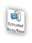
The primary method of converting 2D sketches into 3D geometry, the Boss Extrude feature allows you to add depending on several conditions to your part. You will need to either have a sketch or create a sketch in order to create an extrusion!

Revolve
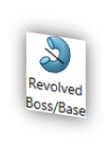
Revolves add or remove material by revolving one or more profiles around a centerline. Use these to create cylindrical or spherical parts in a single feature! A perfect example of a revolve would be a soda can.

Extrude Cut
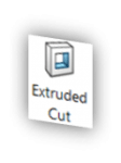
Want to remove some material? The Extrude Cut features allow you to get rid of material on your part. Be aware that you need to have material before you can activate the extruded cut command.

Hole Wizard

If you are looking to make any type of circular hole, look no further! The Hole Wizard contains specifications for the majority of holes, and even lets you bring that information into your 2D drawings automatically. Just select your Hole Type, Size, and Location to make your first hole.


While using these key features is a good starting point, it is not enough. During the SolidXperts courses, we discuss the ins and outs of these features and how to best apply them. Be you want to avoid picking up bad modeling habits!


Step 4: Start Modeling

See that pencil holder on your desk? Model it. What about your phone? Model that too! The more you work to understand completed parts as a combination of extrudes and cuts, the easier it is to CAD. There is no “secret” to getting good at modeling besides practice. At the end of the day, it takes time and a positive attitude to go from a casual user to a  master modeler.

So that is it! If you follow this outline, you will have all of the tools you need to start modeling like a champ. Remember that you are only limited by your own creativity, so have fun and continue to grow. If you need help, feel free to give us at SolidXperts a call (we are the Experts!).

  1. Know your Resources
  2. Learn the UI
  3. Get Comfortable with the Basic Features
  4. Start Modeling

What’s Next? After mastering the above, it is time to explore the more complex features and functions that SOLIDWORKS has to offer. Check out the advanced classes that SolidXperts has to offer like Surfacing, Weldments, Sheet Metal, and more!


SolidXperts teams can help you become true 3D experts! An additional question? Need information?

Contact us! 

SolidXperts team is always there for you!

X_green_halo

Any questions? Need help? Ask one of our experts.

Whether you’re ready to get started or just have a few more questions, you can contact us toll-free:


    Welded Constructions with the SOLIDWORKS Structure System

    BLOG

    Welded Constructions with the SOLIDWORKS Structure System

    [techtips_featured_image_shortcode]

    From the 2004 version of SOLIDWORKS onward, the welded construction function speeds up the creation of assemblies because it allows the representation of assemblies without having to create multiple individual files. But, there is more since version 2019.

    The new “Structure” function allows the creation of welded constructions in a different way. It is not necessary to draw a path for each profile. For example, it is possible to create a starting profile (“Primary Element”) from:

    – From 4 planes;


    – Of a path element (a bit like welded construction);

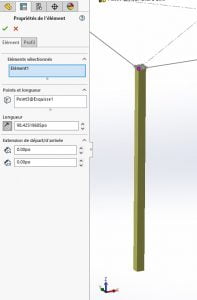
    – By defining a length by selecting only one point (note the absence of a sketch in the requested selection);


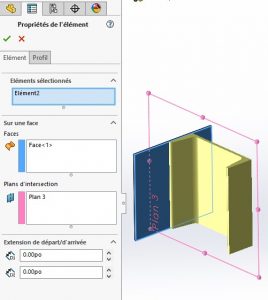
    – By defining an intersection between a face and a plane.


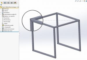
    So, with a few clicks, you can define a structure, including corner treatment:


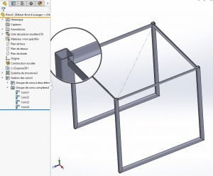
    You can then modify the created structure (in one function!) to change the profiles of certain elements:


    Following the creation of the external shape of the frame, reinforcements or other elements must generally be attached to it. As mentioned above, creation methods using entities other than sketch segments can be used. For so-called “secondary” elements, using the selection of two existing profiles, two methods are possible:

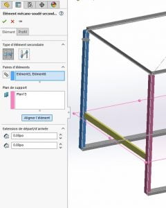
    – Supporting Plan Element” uses an existing plan to position the newly created profile.


    Activating chain selection allows the automatic creation of element pairs when two entities are selected.

    – Between point elements.

    This method has two ways of working, using either distance or length ratio.

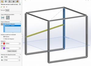
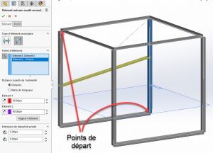
    The first allows the definition of two distances from the starting point of the profiles:


    We can see on the screenshot above that despite the two equally defined distances, the profile is at an angle. The reason for this is that the dimension is defined by the starting point of the profile, which corresponds to the starting point of the sketch, i.e. at the top of the structure for the profile on the left of the screenshot and at the bottom for the profile on the right:


    Just click on the appropriate icons to reverse the directions and thus obtain a secondary profile perpendicular to the primary profiles.

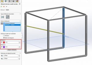
    Ratios (whose value must vary between 0 and 1) of length relative to each previously selected element can also be used. In this way, always taking the direction into account, it is easy to create a spacer that would be on one side at the upper third of a profile and at the lower third on the other.


    As for the creation of a drawing, the operation is the same as for a welded construction.

    All in all, even if you are already using welded construction, this new working method can be confusing at first, but you quickly get used to it and learn to appreciate the lightness of the creation tree it produces. Moreover, just like the welded construction, the result produced is compatible with the BeamCutXperts beam optimization tool.

    For more information visit our SOLIDWORKS product page, or consult an Xpert!

    X_green_halo

    Any questions? Need help? Ask one of our experts.

    Whether you’re ready to get started or just have a few more questions, you can contact us toll-free:
      How 3D Printing Repaired a Broken Water Rower

      BLOG

      How 3D Printing Repaired a Broken Water Rower

      [techtips_featured_image_shortcode]

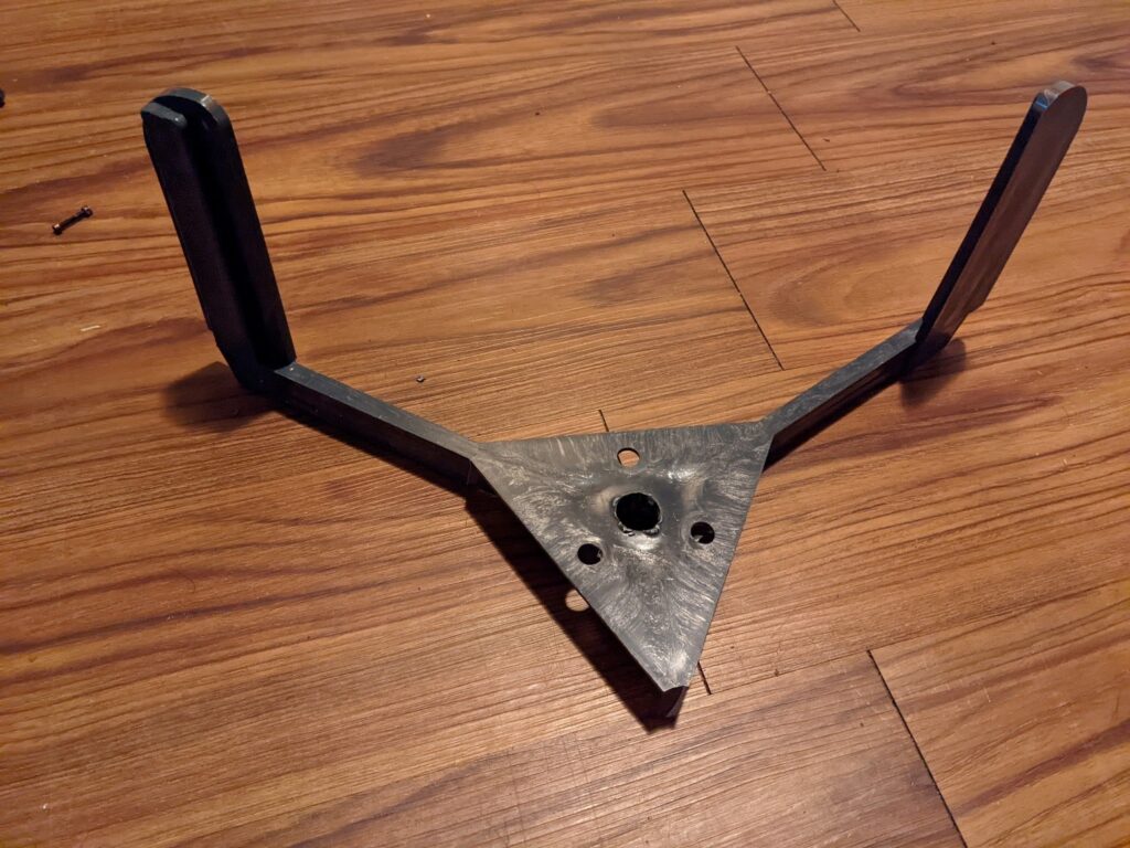
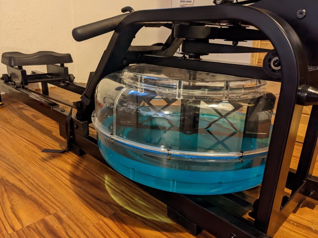
      You might be an engineer – if, you fix broken fitness equipment with CAD and 3D printing. This 3D printing repair case shows just how that was done. It starts with a budget water rower exercise machine that had arm failures in the resistance paddle which spins inside the water tank. Unfortunately, the machine had been purchased early in the year and the paddle arms failed by December.

      Why the Original Water Rower Paddle Failed

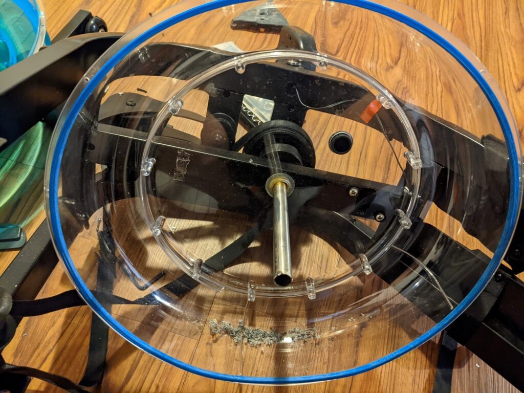
      Upon closer inspection, the arms of the original paddle broke off where the plastic transitions from a thinner beam profile to the larger hub. In hindsight, it could have been predicted by using SOLIDWORKS Flow, Plastics, or Simulation software. However, that discussion will be saved for another article.


      This type of failure makes the component an excellent candidate for 3D printing repair. Rather than simply reproducing the original part, engineers can redesign the weak geometry to create a stronger, more durable replacement.

      Redesigning the Paddle for Improved Performance

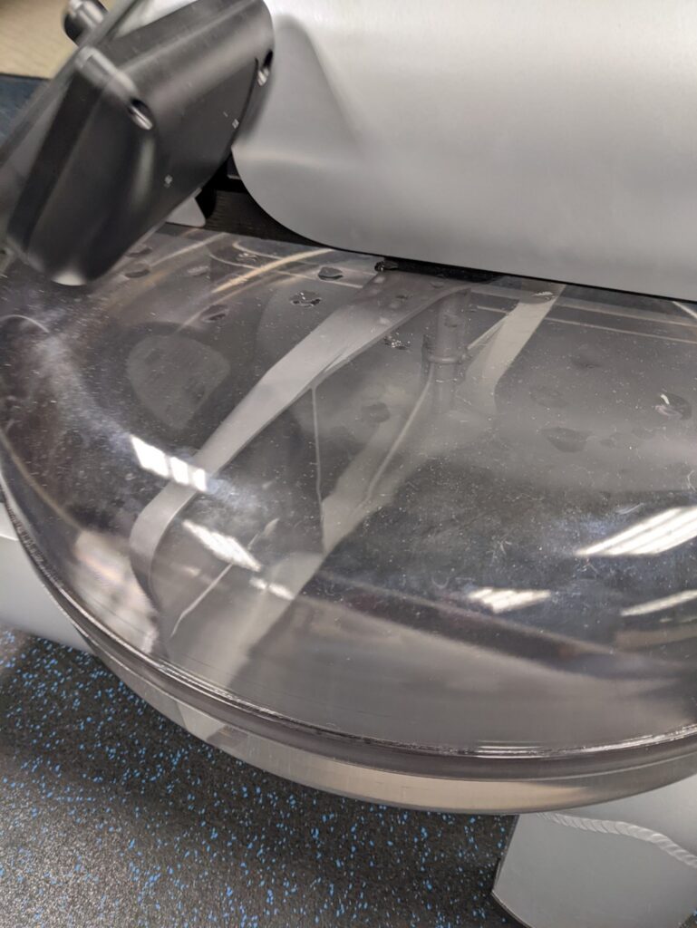
      For the moment, we will focus on designing and producing a 3D printed replacement paddle. The new design is inspired by the paddle used in commercial-grade water rowers found in health clubs.

      To improve the design, the commercial grade water rower has single mixing paddle design that extends across the diameter of the tank. In addition, there are openings between the shaft hub and the scoop ends, but the paddle has solid plastic arms at the top and bottom of the water tank. The budget rower was connected only at the bottom of the water tank leading to increasing offset dynamic loads as athlete exertion increases.

      Optimizing the Design for 3D Printing

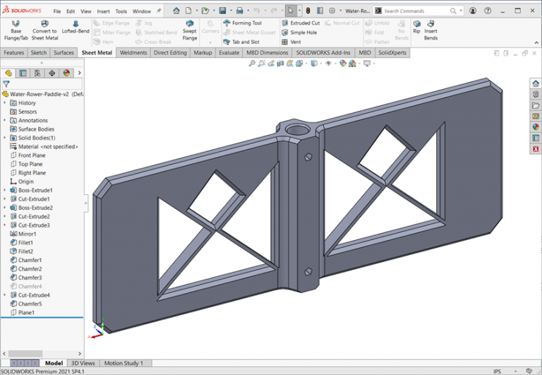
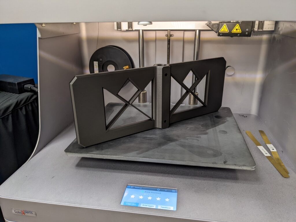
      Although the original design paddle diameter of 18 inches is larger than many 3D printer print volume dimensions, it was possible to get 16 inches diagonally across the build plate. To compensate for the reduced print size, the width of the working portion of the paddle was adjusted, and the solid section was moved to the top. As a result, the 3D printed design maintained a water-displacing surface area similar to that of the original injection-molded paddle.

      Furthermore, by using a pattern of triangle and diamond shapes for the open section, the replacement paddle can be printed without support. Chamfers are used for edge breaks around the edges and openings for better flow characteristics while still being easy to print.


      Finally, the original paddle had a pressed and brazed connection between the paddle and rower shaft.  This was replaced with a pentagon shaped hole to allow for screw fastening to the shaft.

      Choosing the Right Material for 3D Printing Repair

      To maximize durability,  Markforged Onyx filament is used which is a carbon and nylon blend. The wall passes are increased and gyroid infill is used along with maintaining the full paddle width through the paddle cross section.

      Installing the 3D Printed Replacement Part

      Disassembling the original paddle from the rower required several steps. The process involved drilling and using a gear puller to free the shaft before the 3D printed replacement could be installed.


      Once the original component was removed, some additional drilling and bolting allowed the new paddle to be installed on the rower shaft.

      Performance After the 3D Printing Repair

      With a slight adjustment of water volume in the tank, the 3D printed replacement paddle provides the same resistance and workout as the when the machine was new.

      Although the water flow is different with the replacement paddle but the workout is the same. As a result, the repair is done in time for a new year of health resolutions.

      The Value of 3D Printing Repair

      This project demonstrates how 3D printing repair can extend the life of consumer equipment while improving the original design. Rather than replacing the entire machine, a redesigned component restored performance, reduced waste, and created a more durable solution.


      Whether you’re repairing obsolete, damaged, or discontinued components, contact Solidxperts to explore how SOLIDWORKS and industrial 3D printing can provide a practical, cost-effective solution.

      X_green_halo

      Any questions? Need help? Ask one of our experts.

      Whether you’re ready to get started or just have a few more questions, you can contact us toll-free:
        What’s New SOLIDWORKS 2022 – Hit List

        BLOG

        What’s New SOLIDWORKS 2022 – Hit List

        [techtips_featured_image_shortcode]

        Installation –

        Admin Image types (option) Standard, Remote, Compressed

        Remote – allows users to download image from internet / SOLIDWORKS Customer Portal instead of from company VPN

        Compressed – smaller download, but must use full package at each service pack upgrade

        SOLIDWORKS Electrical – new client or server specific installation options (easier for multi-user environments)

        PDM – vault views can now be deployed as part of an Admin Image

        Copy Settings wizardcan now adapt to System Options distributed and locked with Admin Image


        User Interface –

        New message bar pop-up at top of graphics window

        Quick Copy utility for Measure tool – allows 1 click copy of values or values + units

        Command Search now integrated in Shortcut toolbar (and can be directly added to toolbar)

        Drawings saved to PDF can now include the sheet / paper color

        Reference Geometry display and selection during Mate, Measure or Pattern.

        While in the command hover mouse over faces or cylinders press [Q] to momentarily display reference geometry for selection.

        Additional options for Component Tree display to show various combinations of Component Name, Description, Configuration, and Display State.


        Sketching –

        Linear sketch entity is now usable for direction reference in patterns

        Sketch textnow works in patterns


        Parts –

        Coordinate systems – can be set with exact values in 3D space (independent of a geometry reference to select)

        Coordinate systems – can be referenced or selected by its origin, an axis or plane

        Cosmetic Threads – better display, retains proper depth and edge attachment

        Draft Across Parting Lines – now draft can be applied in both directions from a parting line as 1 feature

        External Threaded Stud Wizard – an extension of detailed Thread Feature that builds the stud with threads at 1 time

        Hole Wizard Slots – dimension to arc center option added, hit [Tab] to rotate 90deg while placing feature.

        Hybrid Modeling – allows mesh bodies (after BREP conversion) to be edited with surface features and combined with solid features

        Segmented Mesh bodies – converted mesh bodies can have faces turned into classic BREP

        Mirror about 2 planes – with 1 feature creation

        Rotate Section View– around a hole or axis

        Thickness Analysis – now offers Resolution control with Low, Med, High tessellation sizes


        Model Display –

        Performance improvement for 3D textures and silhouette edges


        Sheet Metal –

        Edge flanges on curves can now apply edit profile to limit the feature extents

        Etched contours on bends (sketch text or split lines) retain display in flattened state


        Structure System & Weldments –

        Structure Systems now supports end caps

        Custom Properties of older version weldments (2017 or earlier) can be upgraded to newer property architecture

        Improvements in Complex Corner property manager

        Ability for multiple secondary members (using between points, or up to member methods)

        Connector Elements for Structure Systems now supported

        Can include cut features as connector is placed.

        ImprovedCustom Properties dialog for Structure Systems and Weldments bodies


        Assemblies –

        (x) Automatically optimize resolved mode, hide lightweight mode

        Improves performance by letting system control lightweight use behind the scenes (behaves as resolved to the user)

        Open Subassemblies in Different Mode– right click option to load subassembly as LDR or Resolved (independent of upper assembly current mode)

        Exclude from BOM – custom configuration property for components

        Configuration Table – Design Table functionality without needing the embedded Excel sheet  (file size / performance / no excel ???)

        Section View – option toexclude failed componentsand still create section view

        Assemblies and components with equations will auto resolveas needed, if loaded lightweight

        Move with Triad– automatically appears when more than 1 component selected

        AdditionalQuick Mates options on In Context Toolbar


        Detailing & Drawings –

        Alternate Position Viewsnow allow cropping

        Predefined Drawing Viewsnow support trimetric, dimetric, or flat pattern types

        Detailing Modeimprovements – available for any version file, Save model data and include standard views performance options added

        Geometric Tolerance frames now build dynamically on screen 

        Radius / Diameter dimension display toggle now on incontext bar for easier access

        Sheet Metal flat pattern views can now show bend lines when sketch display is hidden

        Handling of detailed cut lists within BOMtables is improved

        Symmetric Linear Diameter Dimension is added 


        Import / Export –

        Performance improvements forimport of large DXF/DWG and STEP files

        Ability to select specific IFC Entity types from the files for import

        Assigned colors of entities properly support in DXF/DWG export


        PDM –

        Improvements with Windows AD integration: additional user data fields, profile import, login validation tools

        Improved configuration property managementand control

        Archive Server and User log export capabilities added

        Preview Tab now shows full eDrawings viewer controls

        Performance improvementsfor file operations even when database has higher latency


        Manage –

        UI improvements for BOM, Project Properties, Process Tab and more

        Additional user rights controls over check out of items

        Replace User capability added

        Performance improvements for BOM and Project display as well as PDM check in/out


        Simulation –

        Blended Curvature Based Mesher is now default for new studies

        Bonded and Contactperformance improvements

        Linkage Rod Connector item

        Improved solver performance and automatic solver selection


        Visualize 

        Tools to set camera perspective to matchbackplate

        Shadow catcher property can be assigned to scene elements

        Scenes Tab UI improvements

        Animations improvements for motion studies, key frames and more

        Render Output Viewer – in project viewing, control, and management of renders

        Pattern Tool – replaces and improves prior Formation function (Vee, Circle, Scatter, Grid)


        CAM 

        Toolpath endpointscan be set for a custom color for easier viewing

        Filter for Mill & Turn tools containing specified text string


        Composer –

        Ability to import SOLIDWORKS appearance decals

        Import file versionextensions: ACIS up to 2021 , Creo 7, SOLIDWORKS 2022


        Electrical –

        Links in BOM cells – allows multiple items to reference 1 mfg part

        PDF data file support for Project PDF exports (bind PDF function)

        Multiple UI improvements

        Attribute capability added to Origin & Destination arrows (shows mark of connected component)

        Electrical Content Portalcan now be set as dockable panel in UI

        Improved Connection Point creation


        Inspection –

        New API– auto open SOLIDWORKS files, Balloon drawings, create reports and more

        Standalone now supportsall native SOLIDWORKS files and NX/Unigraphics *.prt files (MBE)

        Smart Extract in standalone has improved recognition and parsing of PDF file content


        MBD 

        HTML(5) exportoption on 3D PDF creation

        Angle Dimension manual annotation for DimXpert added

        Geometric Tolerancingimprovement including ANSI Y14.5 or ISO 1101 release selection


        eDrawings –

        Support for SOLIDWORKS custom file properties when saved as eDrawings files

        Components list UIimprovements


        Flow Simulation –

        Scene Plot utility – stores all displayed plots and model display

        Compare Tool improvements

        Range Function – for handling of transient effects (such as power derating due to temperature calculation)

        Flux Plot – now available within Transient Explorer


        Plastics –

        Symmetric & Cyclic Cavity and Runner Layout tools

        Injection Location Advisor – based on part geometry software selects up to 4 recommended injection locations

        Polymer materials data updates (using latest manufacturer properties)

        SABIC, Polyplastics, Solvay Specialty Polymers, Radici Group, LANXESS

        Improved UI of Plastics Manager Tree

        4K and higher displayresolution support

        Solver performance improvement – cooling calculation time reduced 34%, Fill & Pack reduced 60%


        Routing –

        Flatten Routeimprovements for horizontal selection, and line only output

        Connector backshellsupport added

        Replace Connectorcapability added – preserves line connection where possible  


        SolidXperts teams can help you become true 3D experts! An additional question? Need information?

        Contact us! 

        SolidXperts team is always there for you!

        X_green_halo

        Any questions? Need help? Ask one of our experts.

        Whether you’re ready to get started or just have a few more questions, you can contact us toll-free:
          How to Produce an Adaptive Form with DriveWorks

          BLOG

          How to Produce an Adaptive Form with DriveWorks

          [techtips_featured_image_shortcode]

          By Marco Chery – SolidXperts Application Specialist

          What is an adaptive form?

          DriveWorks projects created using responsive forms adjust their content regardless of the size and orientation of your device screen, whether it is a computer, tablet, or smartphone. This eliminates the need to swipe the web page from left to right to see content and the user’s browsing experience is more intuitive.

          Why should you use them?

          • For the dissemination of DriveWorks projects on the web;
          • Improved user navigation;
          • Access the project anywhere from any device.

          A Few Tips

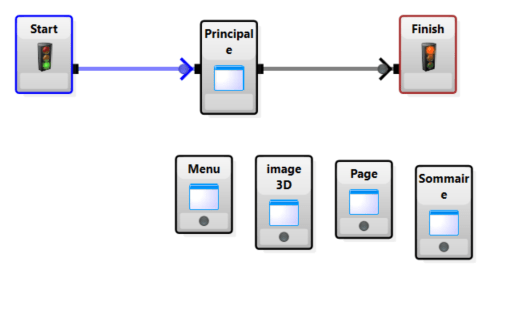
          The easiest way to make your forms responsive is to use Frame Controls on the main page. From this main page, the windows will allow you to see the content of your different forms.

          First, define the location of your viewing windows for the resolution of a desktop computer.

          Second, create a plan to switch these windows to the screen of a phone and tablet.


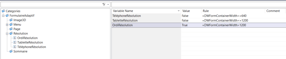
          Third, determine the borders for switching windows between different device resolutions. For this, we use a special DriveWorks variable: FormContainerWidth.

          • Phone Resolution: 320 – 640 pixels
          • Tablet Resolution: 640 -1200 pixels
          • Computer Resolution: 1200+ pixels

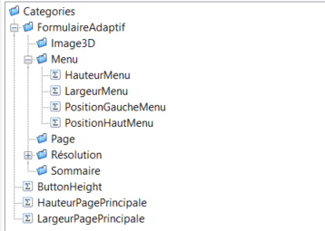
          Fourth, for each zone, we can create variables that will position the window taking into account the different resolutions.

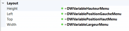
          Finally, we import the variables to the main page, in the layout section for each type of viewing window.

          Conclusion

          This method ensures your DriveWorks project forms are adaptive and attractive, regardless of the device on which they are viewed.

          SolidXperts teams can help you become true 3D experts! An additional question? Need information?

          Contact us! 

          SolidXperts team is always there for you!

          X_green_halo

          Any questions? Need help? Ask one of our experts.

          Whether you’re ready to get started or just have a few more questions, you can contact us toll-free:
            SOLIDWORKS Visualize – Video Decal

            BLOG

            SOLIDWORKS Visualize – Video Decal

            [techtips_featured_image_shortcode]

            By Nikita Lambert – Certified SOLIDWORKS Expert (CSWE) at SolidXperts

            You may have already said that your rendering is acceptable, but that it seems to be missing something, that your image lacks life. SOLIDWORKS Visualize now has the solution for you: You can now create a video decal and apply it to any surface of your model. For example, a cellphone company could put a clip showing the operating system in action on a newly designed device, an animated background plan outside a window, or even a television playing your favorite series! The possibilities are limited only by your imagination.

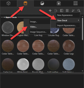
            To take advantage of this 2019 innovation, simply go to your Appearances tab, Add, New Decal, and finally Video. Browse and search for your video file and you need only apply it to your project.

            SolidXperts teams can help you become true 3D experts! An additional question? Need information?

            Contact us! 

            SolidXperts team is always there for you!

            X_green_halo

            Any questions? Need help? Ask one of our experts.

            Whether you’re ready to get started or just have a few more questions, you can contact us toll-free:
              Exporting SOLIDWORKS Visualize to Nvidia Holodeck

              BLOG

              Exporting SOLIDWORKS Visualize to Nvidia Holodeck

              [techtips_featured_image_shortcode]

              By Nikita Lambert – Application Specialist at SolidXperts

              Nvidia has developed a collaboration platform to allow engineering, sales, marketing, and management teams to interact with a design still in the development phase, using virtual reality technology.

              This platform allows you to transport yourself to the interior of a 3D modeled building, in front of a podium showcasing your newest products, or even into a virtual meeting room with your VR headset.
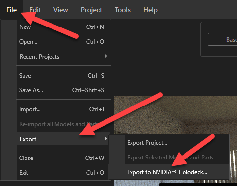
              SOLIDWORKS Visualize can export your completed project to an Nvidia Holodeck-supported format.

              All appearances, environments, and lighting will be automatically recorded, all you have to do is explore the almost infinite possibilities of this new mode of communication.


              SolidXperts teams can help you become true 3D experts! An additional question? Need information?

              Contact us! 

              SolidXperts team is always there for you!

              X_green_halo

              Any questions? Need help? Ask one of our experts.

              Whether you’re ready to get started or just have a few more questions, you can contact us toll-free:
                How to Update SOLIDWORKS PDM Task Add-Ins

                BLOG

                How to Update SOLIDWORKS PDM Task Add-Ins

                [techtips_featured_image_shortcode]

                If you use automated tasks in SOLIDWORKS PDM, such as converting SOLIDWORKS files to PDF, the related task add-ins must be updated whenever you install a new version or service pack. This allows you to benefit from the latest features, improvements, and fixes.

                The same update procedure also applies to Dispatch, the built-in programming add-in used to automate actions in SOLIDWORKS PDM.

                Here’s how to do it:

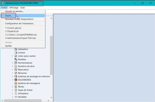
                • PDM Administration Tool > File > Open:
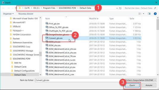
                  Go to > C:\Program Files\SOLIDWORKS PDM\Default Data
                • Open > C:\Program Files\SOLIDWORKS PDM\Default Data\Convert_gb.cex

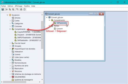
                Here are the complements available and the associated tasks:

                • To update Dispatch, open Dispatch.caf
                • Drag and drop SWTaskAddIn (import only the add-in) from the window on the right, in Add-ins on the left:

                Note: If you have a dedicated workstation that performs tasks, you will need to log out and reconnect to PDM to ensure that you have the correct add-in.

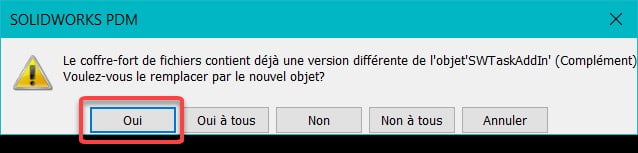
                • Reply Yes to ‘Do you want to replace with the new object?’

                It’s that simple. The add-in is now up-to-date!

                Keep Your SOLIDWORKS PDM Add-Ins Up to Date

                Updating SOLIDWORKS PDM task add-ins and Dispatch helps keep automated workflows reliable after a version or service pack upgrade. Once the new add-in has been imported and the existing object replaced, users can continue running their tasks with the latest improvements and fixes.


                Remember to log out and reconnect to PDM on any dedicated task workstation so the updated add-in is loaded correctly. Need help updating or managing your SOLIDWORKS PDM environment? Contact the Solidxperts team for expert assistance.

                X_green_halo

                Any questions? Need help? Ask one of our experts.

                Whether you’re ready to get started or just have a few more questions, you can contact us toll-free:
                  How do you Install SOLIDWORKS as Quickly as Possible?!

                  BLOG

                  How do you Install SOLIDWORKS as Quickly as Possible?!

                  [techtips_featured_image_shortcode]

                  The SolidXperts Technical Support Team is here to assist with software installations and updates for all clients who have purchased a license with us.
                  You can contact us by telephone at: 1-877-824-3324, by email:
                  soutien@solidxperts.com, or simply submit a request in the Client Portal: https://solidxpertsportal.force.com/support/portal_login

                  Ask us to send you our direct download link for installation files without having to go through the SOLIDWORKS site. Then if you wish, contact us for remote assistance with a member of our support team. We can remotely control your computer if you are not very familiar with the installation process or simply because you want a state-of-the-art installation!

                  We can take this opportunity to install our UtilsXperts toolbox, developed by our team of programmers at SolidXperts. You will be able to optimize your productivity and design products more efficiently, faster, and more profitably.

                  SAVE TIME!

                  For an additional fee, we also offer a hassle-free service to help you centralize your data in order to facilitate the management, customize your settings, and also standardize your data, BOM tables/revisions, and default models for better collaboration within your Engineering team, across your entire CAD system. Contact a Support Team member today for more information!

                  Rather than waste time with lengthy installations on all your stations, let us do it for you!

                  Our Xperts are always ready to assist you.

                  X_green_halo

                  Any questions? Need help? Ask one of our experts.

                  Whether you’re ready to get started or just have a few more questions, you can contact us toll-free:
                    Access your SOLIDWORKS from Anywhere

                    BLOG

                    Access your SOLIDWORKS from Anywhere

                    [techtips_featured_image_shortcode]

                    Written by Tech Support Group Director – Trung Ha

                    Did you know that you can access and use your SOLIDWORKS from anywhere? Users can simply log in with their SOLIDWORKS ID on the MySolidworks website and launch their SOLIDWORKS! SOLIDWORKS online licensing is available to all customers regardless of their subscription status. The SOLIDWORKS Admin can reassign an Online License at any time, as long as the license is not in use by the user.

                    SOLIDWORKS online licensing is a new model that ties one or more licenses of SOLIDWORKS products to a user’s SOLIDWORKS ID. With SOLIDWORKS online licensing, users have the flexibility to install and use SOLIDWORKS products on as many machines as they wish, without having to activate or deactivate machines every time. SOLIDWORKS’ customers can access all the products they are entitled to by simply login in using their SOLIDWORKS ID. All they need is a connection to the internet.

                    The Admin can select an asset and change it back from online licensing to machine activation at any time using the toggle option in the detailed product page if the license is not in use by the user.


                    To create a SOLIDWORKS ID:


                    SolidNetWork Licenses are ideal for medium to large size companies that want to share a pool of licenses over multiple users. On the other hand, single-user licenses with SOLIDWORKS online licensing are ideal for individuals that have their own license and want the flexibility to use SOLIDWORKS on multiple machines.

                    Only one user can be assigned to an Online License product.

                    SOLIDWORKS online licensing is available for the following single-user license products:


                    **Perpetual and temporary licenses are supported. SOLIDWORKS PDM and SolidNetWork Licensing (SNL) are not supported with online licensing. Home Use Licenses (HULs) are not currently supported.

                    Don’t hesitate to call the Technical Support Call Center and let us do it for you!
                    One of our specialists can help you configure it remotely.

                    X_green_halo

                    Any questions? Need help? Ask one of our experts.

                    Whether you’re ready to get started or just have a few more questions, you can contact us toll-free:

                        Download

                          Download

                            Download