By Frédéric Jacques – Application Specialist – SolidXperts
Do you want to avoid designing sheet metal parts beyond the dimensional limits available? Add an alert (sensor) to your SOLIDWORKS model.
How to Add a Dimension Sensor in SOLIDWORKS Sheet Metal
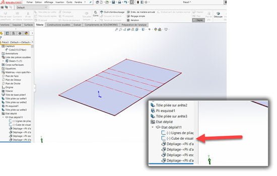
Step 1: Display the View Orientation Cube
Display the flattening of your sheet metal part. Make sure the sketch of the viewing cube is not in hidden mode.
 Step 2: Hide the Volume Body
 Step 2: Hide the Volume Body
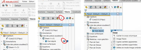
Hide the solid body to show only the fold lines and the viewing cube of the unfolded part. To do so, unfold the display status bar in the creation tree (Feature Manager). Right-click on the body displayed in the open tab and select hide volume body.
 Step 3: Place a Reference Dimension
 Step 3: Place a Reference Dimension
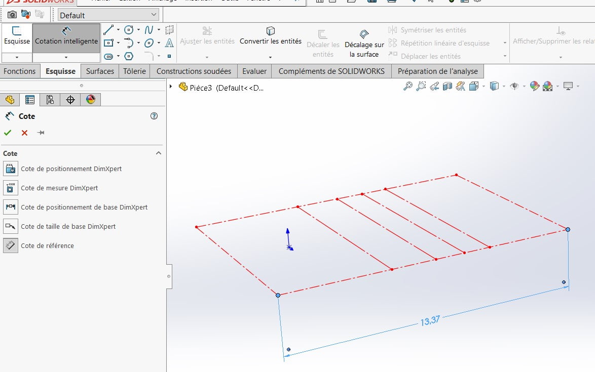
Now you can see the sketch of the viewing cube automatically created by a sheet metal part in SOLIDWORKS. This represents the overall volume of the part and you can place a reference dimension on the length, width, or thickness. Be careful not to select sketches that represent bend lines.
 Step 4: Create a Dimension Sensor
 Step 4: Create a Dimension Sensor
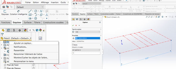
Include a sensor. Right-click on the sensor icon in the creation tree and select “Add a sensor”. Select a dimension sensor and submit the desired conditions.
Sensor type = Dimension
Properties = Select the reference dimension that has been added (13.37″)
Alert = Check the box “Warn me if the value = …”
Select “is greater than” and write the value not to be exceeded. (15″ in the example)
 Step 5: Check Sensor Operation
 Step 5: Check Sensor Operation
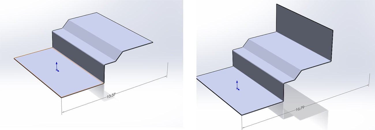
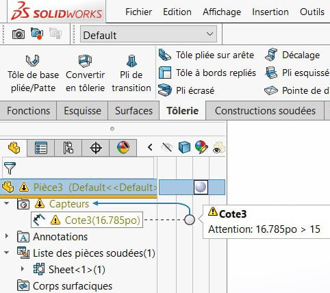
Finally, display the volume body again, and apply any modifications to your part in the folded state. A warning message is then displayed in the shaft if you are no longer within the defined values of the sensor.
Optimize Your SOLIDWORKS Sheet Metal Designs
By adding a dimension sensor to your SOLIDWORKS sheet metal model, you can quickly identify when a part exceeds your manufacturing size limits. This simple check helps prevent design errors, reduces rework, and ensures your parts remain compatible with available equipment.
Need help optimizing your sheet metal workflow in SOLIDWORKS? Contact the Solidxperts team for personalized support and expert guidance.

Any questions? Need help? Ask one of our experts.
Whether you’re ready to get started or just have a few more questions, you can contact us toll-free:

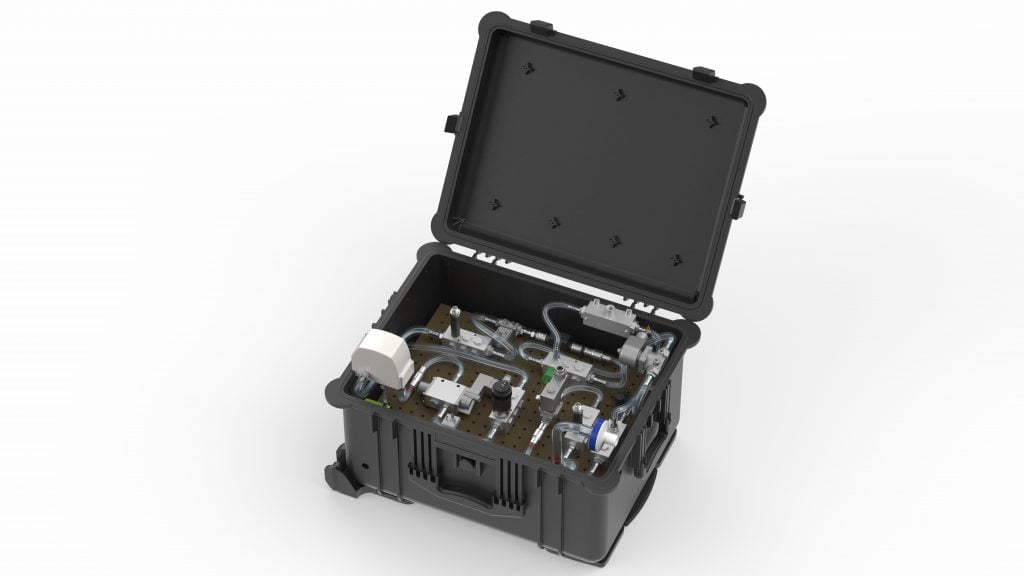 “It feels like drowning is”, the most common report from the COVID-19 patients requiring breathing assistance, and with that imagery, we took inspiration from the simplicity of a scuba breathing apparatus. The SolidXperience Group officially began tackling the problem on March 23rd, ready to help save the world however they could.
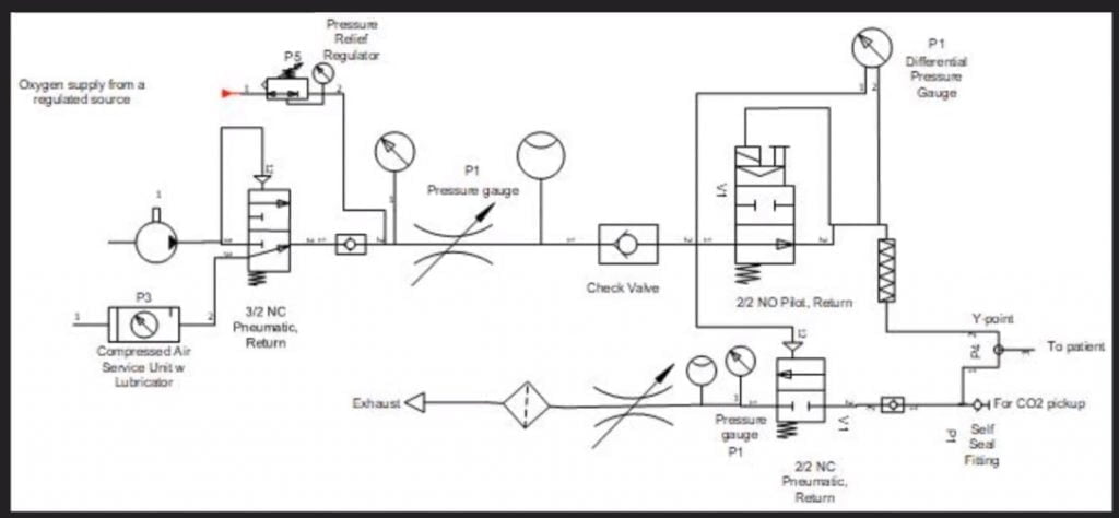 The next step was to analyze the given product specifications and start creating schematic diagrams defining the required parts and showing how those parts interact to create the desired results. With the help of the project’s panel of medical advisors, the group was able to take the initial schematic designs and modify them as a collaborative team. All online!
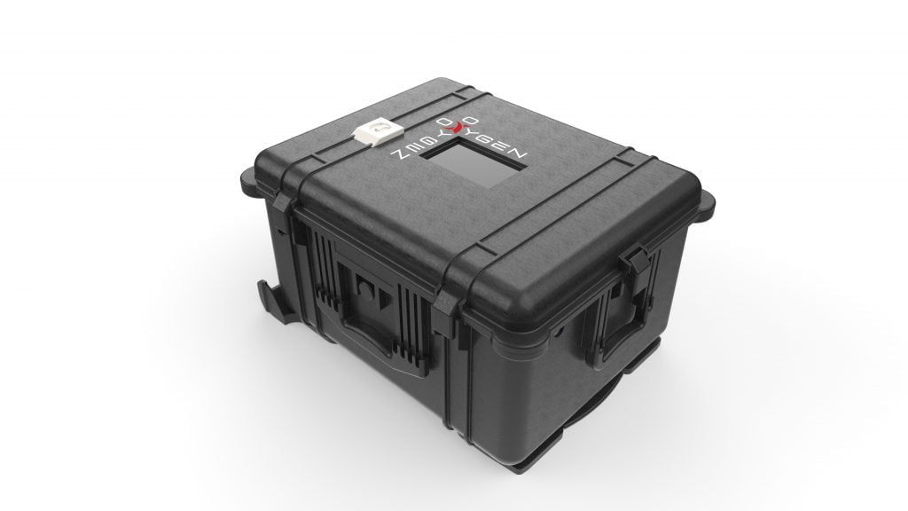
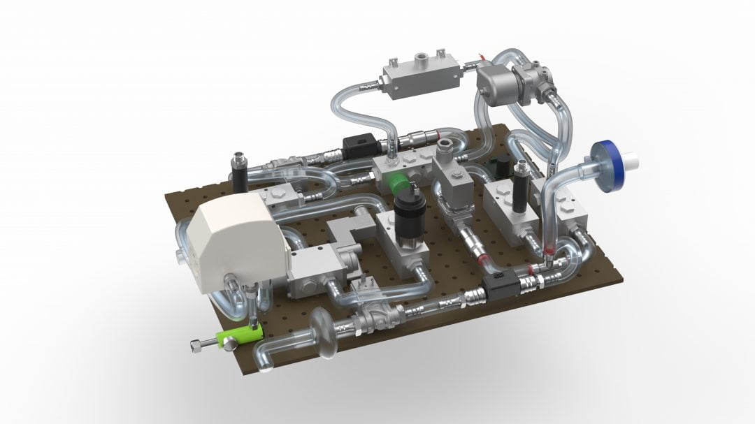 Next, packaging: getting all the required components to fit into a manageable, transportable, robust, easy-to-operate, and reliable case. Under the pressure of the CODE LIFE contest entry submission date of March 31st, this process was successfully started and completed on March 30th. Concurrently, the digital interface was coded to manage the internal valves, solenoids, and sensors necessary to provide a clear and secure on/off readout and warning alarms.
 The fight isn’t over yet, however! In the coming weeks, several more steps need to be taken quickly to meet the hopeful deadline of May 1st for a functioning prototype. As the physical pieces of the first construction are gathered the interface code must be tested and refined, and the assembly must go through a series of tests and simulations to determine that it meets pre-set standards and can be labeled ‘medical grade’.
 Thank you to the following team members and professionals for their part in the success of this project!
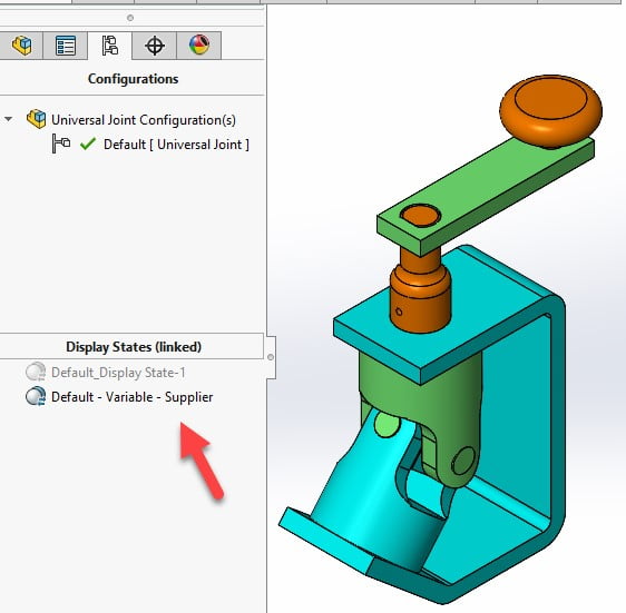
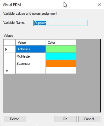
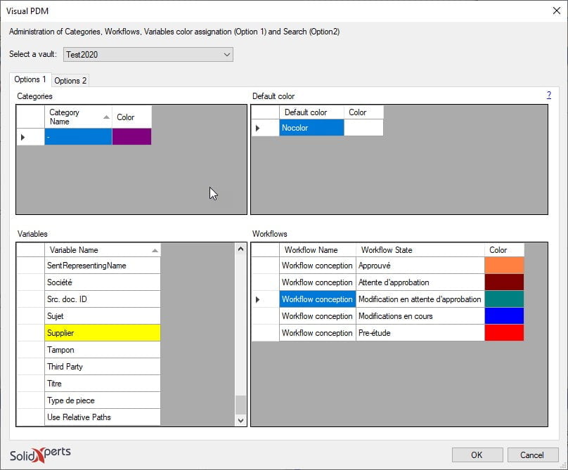 Here is the window that opens to allow you to key in the value and select the “Color” cell.
 By clicking in the “Color” cell you obtain the following window to be able to select the desired color. Click on “Define Custom Colors“ to see the right end side of the window below.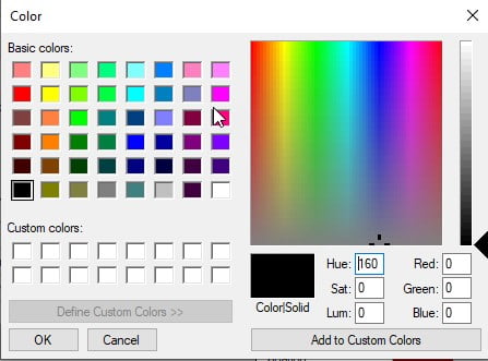

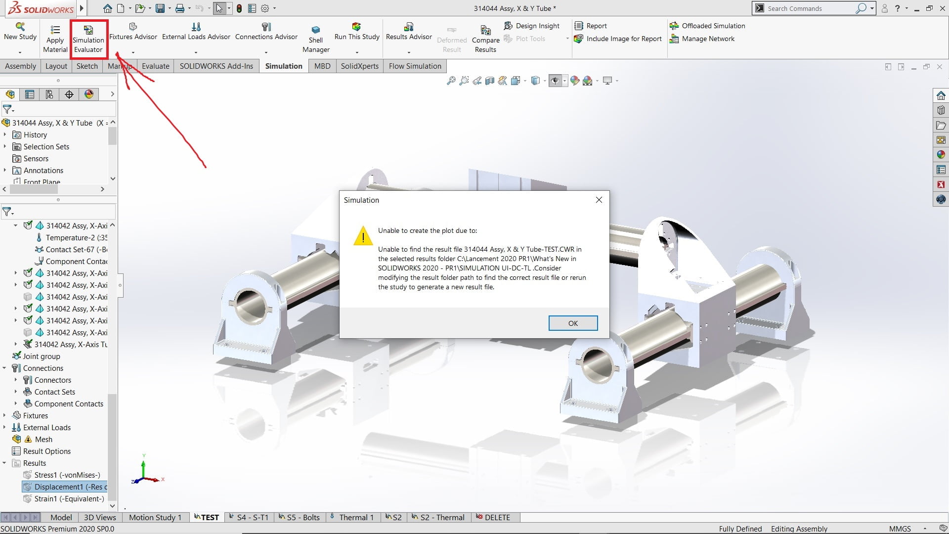
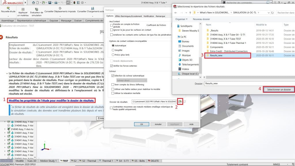
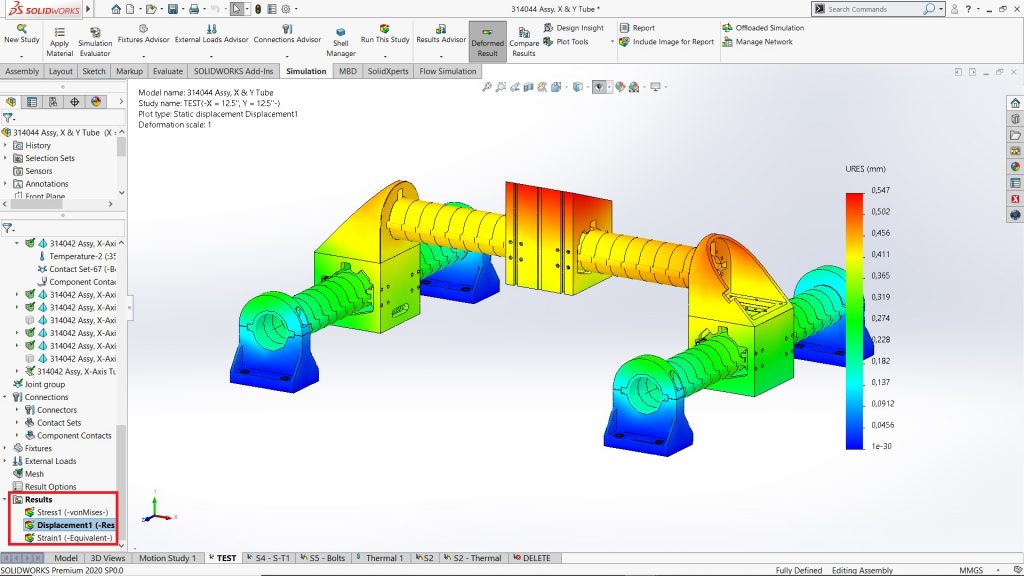
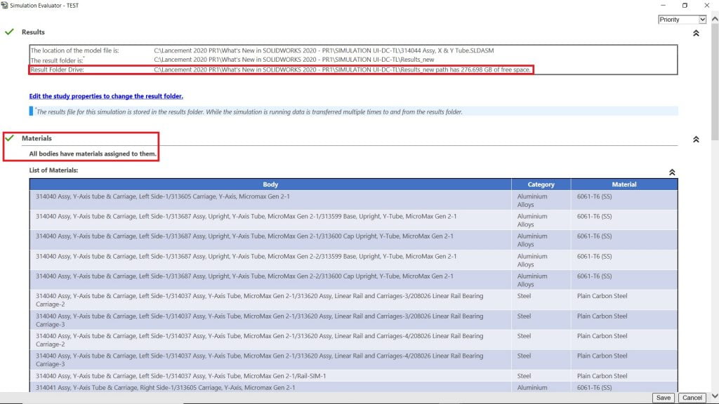
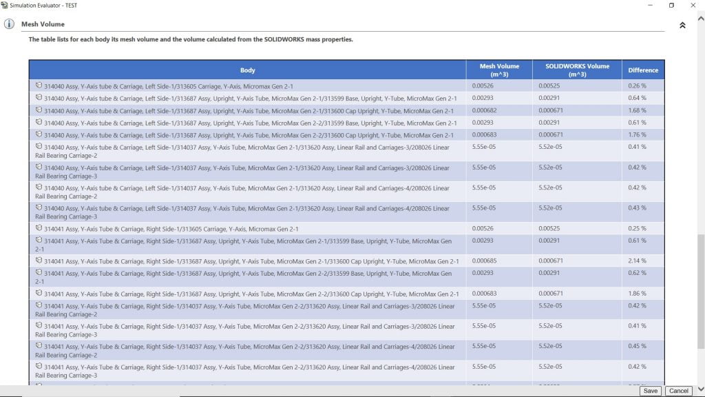 The Simulation Evaluator will enable you to ensure certain essential functions are defined correctly before you run a calculation, to avoid surprises. Reconnecting results files separate from your analyses has never been easier.