SOLIDWORKS Design Checker: Ensure Design Quality at the Source

BLOG

SOLIDWORKS Design Checker: Ensure Design Quality at the Source

[techtips_featured_image_shortcode]

In today’s increasingly demanding industrial design environment, the consistency and quality of CAD files have become critical. Meeting internal standards, drawing conventions, and client specifications is a constant challenge for design teams, especially when multiple engineers collaborate on the same project. This is where SOLIDWORKS Design Checker steps in.

Although often overlooked or underused, this built-in SOLIDWORKS tool allows you to automatically verify that your models comply with predefined design criteria. From dimensioning standards and font usage in annotations to document properties and applied materials, Design Checker delivers a robust quality control process directly within your design workflow.

What is SOLIDWORKS Design Checker?

SOLIDWORKS Design Checker is an add-in module that evaluates whether a part, assembly, or drawing adheres to a set of standardized rules. These rules can be based on your company’s internal procedures, ISO/ANSI standards, or specific client requirements.

The tool functions like an automated reviewer, eliminating repetitive human errors and oversights. It provides a clear report highlighting non-compliant items and offers suggestions for correction.

Key Features of Design Checker

One of the strengths of Design Checker lies in its modularity. You can create Check Files tailored to specific projects, clients, or corporate standards. Here are the main design elements you can verify:

Dimensioning Standards
Ensure that dimension styles (fonts, tolerances, units) conform to ISO, DIN, ASME, or your internal standards.

Text Fonts
Verify that all annotations, dimension texts, and title blocks follow the required font, size, or alignment.

Applied Materials
Confirm that a valid material from your internal library is applied and avoid models with undefined materials.

Sketches and Entities
Analyze sketches to detect open contours, dangling dimensions, or missing geometric relations.

Document Properties
Check for the presence and values of custom properties like part number, project name, author, or creation date.

Drawing Styles
Validate the use of standardized title blocks, sheet formats, and line styles in your technical drawings.

Common Use Cases

Company-Wide Standardization
Within design teams, Design Checker ensures all files follow the same structure, making reviews, reuse, and archiving far easier.

Supplier File Validation
When receiving external CAD files from vendors or subcontractors, you can apply your own rules to verify compliance before integration.

Manufacturing Preparation
Before sending files to the shop floor or outsourcing partners, Design Checker ensures drawings are complete, properly dimensioned, and readable.

Certification Readiness
In industries like aerospace or medical devices, strict documentation standards apply. Design Checker helps enforce these requirements consistently.

How to Use SOLIDWORKS Design Checker

The tool operates on a simple logic: define the rules, then apply them to your documents.

Step 1: Activate the Add-in
Go to Tools > Add-Ins, then check Design Checker to enable it.

Step 2: Create a Check File
Using the Check File Editor, define the rules to be checked—such as units, fonts, properties, etc. These are saved in a .swstd file.

Step 3: Apply to a Document
In the Design Checker tab, load the appropriate .swstd file and launch the analysis. The tool will highlight any deviations and may offer automatic corrections.

Step 4: Review the Report
Design Checker generates a detailed report, enabling you to either manually adjust issues or apply one-click corrections where possible.

Benefits for Design Teams

Time Savings

No need for manual verification, errors are detected in seconds.

Error Reduction

Common issues (missing properties, incorrect fonts, etc.) are caught automatically.

Greater Reliability

Your files are ready for production, certification, or sharing, with guaranteed quality.

Improved Collaboration

Standardized files are easier to hand off between colleagues, vendors, or clients.

Stronger Process Control

Formalizing checks improves the technical credibility and professionalism of your organization.

Limitations and Best Practices

While powerful, Design Checker requires a bit of setup:

  • Creating rules requires thoughtful definition of internal standards.

  • Rules must be kept up to date to remain relevant.

  • The tool works best in structured environments with clearly defined design practices.

However, once these steps are in place, Design Checker becomes a powerful asset in your CAD toolkit.

Wrapping Up: The Value of Design Checker

SOLIDWORKS Design Checker is more than just a verification utility; it’s a built-in quality assurance system for your CAD models. By incorporating it into your workflow, you ensure that every design meets your standards, is ready for production, and free of preventable errors.

The Solidxperts team is here to help you get the most out of SOLIDWORKS Design Checker, from setup and customization of rule sets to best practices for team adoption.

FAQ

Is Design Checker available in all versions of SOLIDWORKS?

SOLIDWORKS Design Checker is included in SOLIDWORKS Professional and Premium. It is not available in the Standard edition.

Can the SOLIDWORKS Design Checker automatically fix detected issues?

Yes, for many items such as dimension styles, fonts, or document properties, the tool offers automatic correction options.

Can verification rules be shared between team members?

Absolutely. .swstd rule files can be stored on a server or shared network folder, allowing everyone to work from the same standards.

Can it be used on assemblies and drawings?

Yes. Design Checker works on parts, assemblies, and drawing files.

Does it require advanced CAD knowledge to use?

No. Once configured, SOLIDWORKS Design Checker is straightforward to use. However, setting up the initial rule set does require a solid understanding of your company’s standards and SOLIDWORKS property management.


Alain

Alain Provost

Senior Technical Sales Executive

X_green_halo

Any questions? Need help? Ask one of our experts.

Whether you’re ready to get started or just have a few more questions, you can contact us toll-free:

    Introducing ToolXperts for SOLIDWORKS: Fewer Clicks, Greater Impact

    BLOG

    Introducing ToolXperts for SOLIDWORKS: Fewer Clicks, Greater Impact

    [techtips_featured_image_shortcode]

    ToolXperts is a suite of automation tools built for SOLIDWORKS users who want to speed up design workflows and reduce repetitive tasks. You’re already familiar with SOLIDWORKS, the industry-standard CAD software used globally to design, model, and document innovative products. Like many engineers and designers, you may already be using it to its full potential. Yet, repetitive tasks can still slow you down.

    That’s where ToolXperts comes in. Designed by CAD specialists and developed by the Solidxperts team, these tools help you save valuable time by automating your most tedious daily operations: DXF file generation, drawing creation, BOM calculations, linear nesting, and much more.

    Why Automate in SOLIDWORKS with ToolXperts?

    Do you spend hours creating technical documentation? Are you still manually exporting sheet metal parts to DXF? Managing cut lengths for structural members in Excel?

    These repetitive tasks cost you time and increase the risk of human errors that can become costly. In today’s landscape of skilled labor shortages, tight deadlines, and constant pressure on profitability, every minute matters.

    What you need are tools that work for you: fewer clicks, fewer errors, more time for design.

    ToolXperts: Custom Solutions from SOLIDWORKS Experts

    ToolXperts are not generic macros. They are the result of more than 25 years of CAD experience and real-world feedback from industrial design professionals.

    Developed by the Solidxperts team, these tools are seamlessly integrated into SOLIDWORKS, respecting your workflows and standards while eliminating unnecessary steps.

    Each tool was born from real-world use cases, driven by clients who needed better efficiency, faster ROI, and smoother processes.

    Even if only one tool fits your need, it can pay for itself quickly by saving you time every single day.

    Popular ToolXperts Features for SOLIDWORKS

    Automatic DXF Export for Sheet Metal or Plates (CutXperts)

    CutXperts from ToolXperts

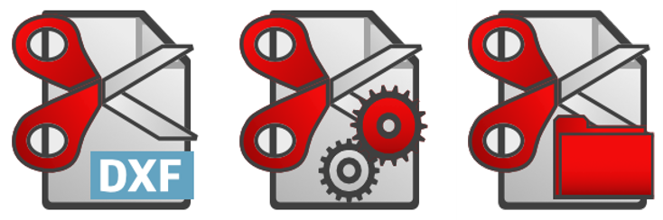
    Gone are the days of opening each part, flattening the model, and launching a manual export. CutXperts by Solidxperts:

    • Automatically detects sheet metal parts or those with a custom property
    • Flattens them
    • Exports clean DXF files in one click

    Ideal for fabrication shops or fast-paced subcontractors.

    Automated Drawing Generation

    This smart module helps you generate part or assembly drawings using:

    • Your custom templates
    • Your predefined views
    • Your preferred scales
    • Your standard annotations

    Perfect for standardizing deliverables and saving hours on drawing tasks.

    Weldment Tool and Linear BOM (BeamcutXperts)

    BeamcutXperts from ToolXperts

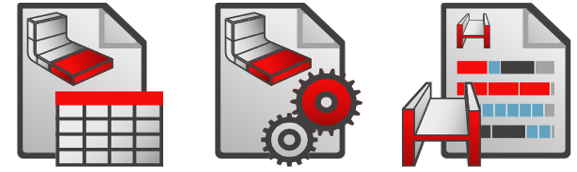
    If you work with tubes, bars, or profiles, this tool:

    • Generates a dedicated bill of materials
    • Calculates raw lengths with tolerances
    • Performs optimized linear nesting to minimize material waste

    Useful for reducing raw material purchasing costs.

    More SOLIDWORKS Automation Features from ToolXperts

    • Automatic file conversion
    • Cleanup of unnecessary custom properties
    • Smart file duplication
    • Automated file naming and archiving

    Every click saved is time reclaimed for design.

    A User Interface Designed for Designers

    Built by SOLIDWORKS users for SOLIDWORKS users, ToolXperts features a user-friendly interface that requires no programming knowledge.

    • Clean, intuitive, integrated interface
    • No steep learning curve
    • Complete documentation
    • Training and support available

    Most importantly, you’re not alone. The Solidxperts team is available to help you integrate the tools into your workflow and even customize them to your unique needs.

    Time Savings and ROI with ToolXperts for SOLIDWORKS

    Picture this: You’re working on a project with dozens of sheet metal parts. Without CutXperts, you must open each part, create a flat pattern, generate the DXF, name it properly, and repeat the process for every update. With CutXperts, one click and your entire DXF package is ready for the cutting shop.

    Example ROI Calculation:

    • 5 minutes saved per part
    • 50 parts per project
    • 10 projects per year

    That’s over 40 hours saved annually with just one tool.

    And that’s just one example.

    What You Gain with ToolXperts

    • Time – Each tool is designed to eliminate repetition and free up your design hours
    • Consistency – All your deliverables follow the same standards
    • Profitability – Less waste, fewer errors, more productivity
    • Peace of Mind – You work with reliable, supported, and regularly updated tools

    The ToolXperts Advantage

    Whether you’re managing hundreds of parts or streamlining a small batch of custom designs, ToolXperts gives you the edge. By minimizing manual effort and standardizing key processes, these tools help engineers focus on what really matters: delivering quality designs, faster.

    With solutions built directly into SOLIDWORKS, supported by experts who understand your challenges, ToolXperts makes advanced automation accessible and practical for every team. From first use, you’ll notice the time savings, and over time, the gains in efficiency, accuracy, and consistency will transform your daily operations.

    FAQ

    Are ToolXperts compatible with all SOLIDWORKS versions?

    Yes, our tools are compatible with recent versions of SOLIDWORKS and are updated regularly

    Do I need to be a programmer to use them?

    No. ToolXperts are built for engineers, designers, and technicians. No coding knowledge required.

    Can these tools be customized to fit our internal processes?

    Absolutely. Our team can tailor existing tools or develop new ones to meet your specific needs.

    How can I test them before purchasing?

    Contact our team for a free, no-obligation demo. We’ll show you the tools in action, with real project examples.


    Alain

    Alain Provost

    Senior Technical Sales Executive

    X_green_halo

    Any questions? Need help? Ask one of our experts.

    Whether you’re ready to get started or just have a few more questions, you can contact us toll-free:
      FeatureWorks in SOLIDWORKS: How to Recover Design Intelligence from STEP and IGES Files Efficiently

      BLOG

      FeatureWorks in SOLIDWORKS: How to Recover Design Intelligence from STEP and IGES Files Efficiently

      [techtips_featured_image_shortcode]

      In the day-to-day work of a designer or engineering office, it’s common to receive 3D files from other CAD software. Fortunately, universal formats like STEP, IGES, or Parasolid allow for model exchange without geometry loss.

      However, they present a major challenge: importing them into SOLIDWORKS strips away the feature tree, turning them into ‘dumb solids’ that are difficult to edit efficiently.

      So, how can we recover the design intelligence behind a simple imported solid? The answer lies in one word: FeatureWorks.

      Put simply, this SOLIDWORKS add-in enables automatic recognition of design features (holes, bosses, fillets, chamfers, etc.) from an imported body.

      As a result, users can reconstruct a feature tree and thus modify, parameterize, or even automate the imported part as if the user had created it natively in SOLIDWORKS.

      In this article, discover how to use FeatureWorks, its benefits, limitations, and real-world applications. It’s a powerful yet often underestimated tool for reverse engineering and collaborative CAD workflows.

      What Is FeatureWorks?

      Put simply, SOLIDWORKS developed FeatureWorks to bring intelligence back to 3D files that users import from other platforms. This add-in primarily functions by recognizing design features either automatically or interactively, depending on user preference

      Typically, when you import a STEP, IGES, or Parasolid file, SOLIDWORKS creates a single solid body with no recognizable features. To address this, FeatureWorks analyzes the geometry to reconstruct, as accurately as possible, the original design elements: sketches, extrusions, holes, fillets, chamfers, and more.

      It’s important to note that FeatureWorks is included with SOLIDWORKS Standard, Professional, and Premium. However, it’s not enabled by default. You must activate it manually through Tools > Add-ins.

      Moreover, supported formats include:

      • STEP (.step, .stp)
      • IGES (.iges, .igs)
      • Parasolid (.x_t, .x_b)
      • SAT, VDAFS, and others

      Consequently, FeatureWorks is especially useful for reverse engineering and working with collaborators who use other CAD platforms.

      Why Use FeatureWorks?

      There are several reasons why FeatureWorks is a valuable tool in a professional CAD workflow:

      Save Valuable Time

      First of all, manually recreating the feature tree of an imported part can be tedious. FeatureWorks offers an automatically generated base of features that you can edit or expand. Therefore, it saves a considerable amount of time, especially for simple to moderately complex parts.

      Edit Parts from Other CAD Software

      Once FeatureWorks recognizes the geometry, the imported part behaves like a native SOLIDWORKS model. As a result, you can make design changes without starting from scratch.

      Reverse Engineering and Legacy Updates

      Additionally, companies with libraries of non-parametric or scanned geometry can use FeatureWorks to restore design intent. This makes it ideal for legacy file updates and engineering change workflows.

      Prepare Models for DriveWorks

      Finally, if you use DriveWorks to automate your designs, FeatureWorks helps convert a “dumb” STEP file into a parametric model, ready for automation.

      How to Use FeatureWorks in SOLIDWORKS

      Here’s a step-by-step guide to getting the most out of FeatureWorks:

      1. Activate FeatureWorks

      • Go to Tools > Add-ins
      • Check FeatureWorks (and optionally, “Start Up” to load at SOLIDWORKS launch)

      2. Import the STEP File

      • Go to File > Open, and select a STEP, IGES, or .X_T file
      • In the Import Options dialog, check Recognize Features to launch FeatureWorks automatically

      3. Choose Between Automatic or Interactive Recognition

      • Automatic Recognition: SOLIDWORKS detects and reconstructs features without user input
      • Interactive Recognition: You manually select which features to recognize (slower but more accurate)

      4. Explore the Options

      • Choose which types of features to recognize: holes, bosses, fillets, chamfers, etc.
      • Optionally retain a copy of the original solid body (useful for validation)

      5. Result: A Partial or Full Feature Tree

      Once recognition is complete, a feature tree appears in the FeatureManager Design Tree. You can edit feature parameters, add or delete features, just as you would with any SOLIDWORKS model.

      Limitations and Best Practices

      Incomplete or Inaccurate Recognition

      Keep in mind, FeatureWorks can’t detect everything. The more complex the part (organic shapes, surfacing, molded components), the less reliable the results. Therefore, it’s best used on machined or welded parts with simple, regular geometry.

      Clean the File Before Recognition

      Before running FeatureWorks:

      • Remove unnecessary entities (logos, engravings, markings)
      • Simplify geometry for easier detection

      Manually Verify Each Feature

      After recognition, always review the results. Some dimensions or sketches may be slightly off. A quick manual validation step ensures the model is reliable for downstream tasks such as automation, simulation, or manufacturing.

      Real-World Use Cases

      Precision Machining Subcontractor

      A machine shop regularly receives STEP files from clients. Using FeatureWorks, it automatically recognizes standard hole and milling features for seamless integration into SOLIDWORKS CAM machining operations.

      Industrial Design Office

      An engineering firm receives 3D files from a German supplier in IGES format. With FeatureWorks, they can modify the geometry immediately. As a result, there’s no need to wait for the supplier to resend a modified file, boosting independence and responsiveness.

      Catalog Modernization

      A company wants to update old, non-parametric CAD files. To do so, it uses FeatureWorks to rebuild features and integrate them into a DriveWorks configurator for automated part generation.

      FeatureWorks, A Tool to Discover or Rediscover

      In conclusion, FeatureWorks is often overlooked or underutilised, yet it can be a powerful productivity tool for engineering teams working with imported files.

      In just a few clicks, it transforms a static “dumb” model into an intelligent, editable, and automatable SOLIDWORKS part.

      Whether you’re a designer, subcontractor, or reverse engineering specialist, take the time to explore this add-in. And if you’d like to go further, consider attending a training course or contact us with your questions.

      FAQ

      What’s the difference between FeatureWorks and standard STEP import?

      By default, importing a STEP file into SOLIDWORKS creates a single “dumb” solid with no feature tree. This means the part lacks editable features and parametric relationships.

      However, by enabling FeatureWorks, you can detect and reconstruct key features such as extrusions, holes, and fillets.

      As a result, it becomes much easier to edit, parameterize, and adapt the part, just like a native SOLIDWORKS model.

      Is FeatureWorks included in all SOLIDWORKS versions?

      FeatureWorks comes bundled with SOLIDWORKS Standard, Professional, and Premium licenses.

      However, since it’s not active by default, users must enable it manually via Tools > Add-ins before use.

      How reliable is automatic feature recognition?

      It depends on part complexity. FeatureWorks works best on machined parts with standard geometry.


      However, for complex or organic parts, such as castings, injection-molded components, or surface-based geometry, recognition may be partial or inaccurate.


      In these cases, it’s advisable to use interactive mode or reconstruct features manually.

      Can FeatureWorks be used on STEP assemblies?

      No.

      Important to note: FeatureWorks only works with individual parts. If you’re dealing with a STEP assembly, you’ll need to open each component separately and apply FeatureWorks to each one.

      Can FeatureWorks detect constraints or sketch relations?

      No, it does not. While FeatureWorks can recognize solid features, it does not recreate sketch constraints or parametric relations.

      Therefore, once recognition is complete, it’s advisable to manually review and add necessary constraints.

      Can FeatureWorks be used with DriveWorks?

      Yes and it’s an excellent use case!

      Once a part is imported and recognized using FeatureWorks, it can be parameterized and automated using DriveWorks.

      As a result, this turns imported geometry into reusable components for product configurators.

      What file formats are supported by FeatureWorks?

      FeatureWorks supports the following:

      • STEP (.stp, .step)

      • IGES (.igs, .iges)

      • Parasolid (.x_t, .x_b)

      • SAT, VDAFS

      However, to ensure proper recognition, the file must contain a valid solid body. Without it, FeatureWorks cannot accurately detect or reconstruct design features.


      Alain

      Alain Provost

      Senior Technical Sales Executive

      X_green_halo

      Any questions? Need help? Ask one of our experts.

      Whether you’re ready to get started or just have a few more questions, you can contact us toll-free:

        5 Signs Your Team Has Outgrown Your Engineering DMS

        BLOG

        5 Signs Your Engineering Team Has Outgrown Shared Drives and Need an Engineering Data Management System

        [techtips_featured_image_shortcode]

        It’s a tale as old as time, or at least as old as networked computers: the shared drive. For many engineering teams, it’s the go-to solution for storing CAD files, design documents, and project data. And for small teams or simple projects, it can work just fine. But what happens when your team grows, your projects become more complex, and the demands on your data management system escalate? Eventually, that familiar shared drive starts to feel less like a trusty companion and more like a tangled mess.

        At Solidxperts, we’ve seen it countless times. Teams reaching a tipping point where their current system just can’t keep up. If you’re nodding along, wondering if your team has hit that wall, you’re in the right place. Let’s dive into five clear signs that your engineering team has well and truly outgrown shared drives and is ready for a more robust engineering data management system.

        1. The Chaos of Version Control: Is That the Latest Revision?!

        Ah, the eternal question: “Is this the latest version?” If your team’s internal communication often revolves around verifying file versions, whether it’s through frantic emails, instant messages, or even shouting across the office, then you’ve likely encountered the first major sign of outgrowing shared drives.

        Think about it. On a shared drive, everyone saves their work, often with cryptic file names like PartA_v1.sldprt, PartA_final.sldprt, PartA_final_final.sldprt, or my personal favorite, PartA_really_final_v2.sldprt. It’s a breeding ground for confusion. Engineers inadvertently work on outdated versions, leading to wasted effort, costly rework, and even manufacturing errors. You might even find yourself duplicating work because someone couldn’t find the existing design.

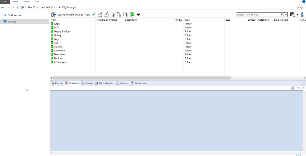
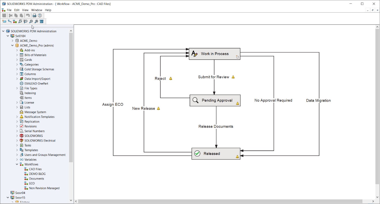
        A proper engineering data management system like SolidWorks PDM or the 3DEXPERIENCE provides a single source of truth. It tracks every revision, every check-in, and every change, ensuring that everyone is always working on the most up-to-date version. No more guessing games, no more “who saved what where?”. Just clear, unambiguous version control.

         Engineers confused by multiple versions of a CAD model, highlighting version control issues on shared drives

        2. The Search Party Dilemma: Where Did That File Go in Your Engineering Data Management System??

        How much time does your engineering team spend looking for files? Be honest. Is it minutes, hours, or even days a week? If searching for specific parts, assemblies, or drawings feels like embarking on a digital archaeological dig, your shared drive is likely holding you back.

        Shared drives rely heavily on human organization, which, let’s face it, is rarely perfect. Files get saved in the wrong folders, buried in sub-sub-folders, or named inconsistently. When a project spans multiple team members and several years, finding an old design becomes an exercise in frustration. Imagine needing a specific bolt design from a project five years ago. On a shared drive, that could mean sifting through hundreds of folders, hoping someone named it logically.

        A engineering data management system brings powerful search capabilities to the table. You can search by custom properties, part numbers, descriptions, or even by “where used”, instantly finding all instances of a specific component across different assemblies. This drastically cuts down on search time, allowing your engineers to focus on what they do best: designing and innovating.

        3. Collaboration Headaches: “Who’s In This File?”

        When multiple engineers need to work on the same project, or even the same assembly, simultaneously, shared drives quickly reveal their limitations. The “file in use” error message becomes a dreaded sight, forcing engineers to wait, or worse, copy files locally and risk creating divergent versions.

        Multiple engineers struggling to collaborate on a single design highlights the limitations of shared drives and the need for an engineering data management system to enable seamless teamwork.

        Imagine two engineers needing to modify different parts of a large assembly. On a shared drive, one engineer might open the assembly, locking it for others. The second engineer is then left waiting, or they make a local copy, make their changes, and then face the monumental task of merging those changes back into the master assembly without overwriting someone else’s work. This scenario is a recipe for errors, frustration, and significant delays.

        Robust engineering data management systems are built for collaborative environments. They employ a check-in/check-out system, ensuring that only one person can actively modify a file at a time, while others can still access and view it. When a file is checked out, it’s clear who is working on it. This streamlines workflows, prevents accidental overwrites, and ensures that everyone is working from the same baseline. To learn more about how SolidWorks PDM facilitates collaboration, check out our blog post on Simplifying Product Development with SOLIDWORKS PDM.

        4. The Security Scares: Who Has Access to What?

        Data security is paramount, especially in engineering. Intellectual property, proprietary designs, and confidential project information need to be protected. On a shared drive, managing access permissions can be a nightmare. It’s often a case of all-or-nothing access, or a complex web of individual folder permissions that are difficult to maintain and audit.

        As your team grows, ensuring that only authorized personnel have access to sensitive data becomes increasingly challenging. Who can view this specific project? Who can modify that particular drawing? What if someone accidentally deletes a critical file? These are questions that keep engineering managers up at night when relying solely on shared drives.

        An engineering data management system offers granular control over access rights. You can define specific user roles and permissions, ensuring that only the right people have access to the right information. This not only protects your valuable intellectual property but also helps maintain compliance with industry standards and regulations. Furthermore, it provides an audit trail, so you can see who accessed or modified what, and when.

        5. Audit Trails and Compliance Headaches: Proving Your Process

        In today’s regulatory environment, traceability and accountability are more important than ever. Whether it’s for internal quality control, industry certifications, or customer requirements, being able to demonstrate your design process, changes made, and who made them, is crucial. Shared drives offer little to no inherent audit trail.

        If an auditor asks for the history of a specific design change, or if you need to prove compliance with certain standards, digging through emails, meeting notes, and “last modified by” dates on a shared drive is a time-consuming and often unreliable process. It’s like trying to reconstruct a complex puzzle with half the pieces missing.

        A robust engineering data management system automatically logs every action. Every check-in, check-out, version creation, and modification is recorded. This creates a comprehensive and unalterable audit trail, making it easy to prove compliance, analyze design evolution, and troubleshoot issues. This level of traceability can be a game-changer for quality assurance and certification processes.

        The Bottom Line: Shared Drives Can’t Compete with an Engineering Data Management System

        If you’ve recognized your team in one or more of these signs, don’t worry, you’re not alone. Many companies reach a point where the informal system of shared drives simply can’t keep up with the demands of modern product development. The good news is, there’s a solution.

        Transitioning to a dedicated engineering data management system like SolidWorks PDM or the 3DEXPERIENCE isn’t just about organizing files; it’s about empowering your team, streamlining your workflows, reducing errors, and accelerating your time to market. It’s an investment that pays dividends in efficiency, accuracy, and peace of mind.

        Ready to explore how a robust engineering data management system can transform your engineering operations? Don’t let shared drives hold your team back any longer.

        Contact us today for a personalized consultation and demonstration of how SolidWorks PDM or 3DEXPERIENCE can address your team’s specific data management challenges.


        Riccardo

        Riccardo Biciola

        Solutions Specialist

        X_green_halo

        Any questions? Need help? Ask one of our experts.

        Whether you’re ready to get started or just have a few more questions, you can contact us toll-free:

          Enhance the Realism of Your Renders in SOLIDWORKS Visualize

          BLOG

          Enhance the Realism of Your Renders in SOLIDWORKS Visualize

          [techtips_featured_image_shortcode]

          Is your SOLIDWORKS Visualize render not realistic enough?

          After weeks of design, engineering, and modeling in SOLIDWORKS Visualize, your project is finally ready to present. It is time to share and communicate your concept with others.

          You import your model into SOLIDWORKS Visualize to generate attractive images, but the result lacks realism.

          Why is your final render in Visualize not meeting expectations? This article explores common issues, practical solutions, and advanced techniques, including the use of PBR materials, to help you create photorealistic renders in SOLIDWORKS Visualize.

          Factors That Can Undermine Realism in SOLIDWORKS Visualize

          Several elements can affect the quality of your renders in SOLIDWORKS Visualize. Here are some of the most common:

          Is your scene lighting underwhelming in SOLIDWORKS Visualize?

          Lighting is a critical factor in SOLIDWORKS Visualize. Using the default lighting imported from SOLIDWORKS may limit your scene’s visual potential. Creating custom lighting directly in Visualize is often the better option, as it gives you greater control over shadows, diffusion, and reflections.

          Is the model not detailed enough?

          Some modeling features may not be necessary for manufacturing in SOLIDWORKS, but they can be essential for photorealistic rendering. Sharp edges, chamfers, and fine surface details can significantly enhance the visual richness once imported into Visualize.

          Is your scene composition lacking?

          Scene layout, camera angle, and framing have a major influence on the quality of your render. Use photography principles such as the rule of thirds and depth of field. Adjust your camera settings in SOLIDWORKS Visualize to enhance the visual impact.

          PBR Materials: The Key to Realism in SOLIDWORKS Visualize

          If your render still seems flat even after optimizing lighting, modeling, and composition, it is time to focus on materials.

          Since 2024, SOLIDWORKS Visualize has supported PBR (Physically Based Rendering) materials. These are widely used in professional rendering engines because of their ability to mimic realistic material behaviors.

          Benefits of Using PBR Materials in SOLIDWORKS Visualize

          • Flexible parameters: PBR materials make it easy to modify the appearance of a surface. You can switch from metal to plastic just by adjusting a few settings. Often, you can reuse textures to generate entirely different-looking materials.

          • Consistent results: PBR materials provide dependable, realistic results across different lighting and environmental conditions. When configured properly, they behave accurately whether used in indoor or outdoor scenes with artificial or natural lighting.

          • Standardized methods: You do not need to start from scratch. PBR materials follow standardized formats, making them compatible with many 3D software applications. Because they are widely adopted, it is easy to find textures that work with them.

          PBR Materials in SOLIDWORKS Visualize

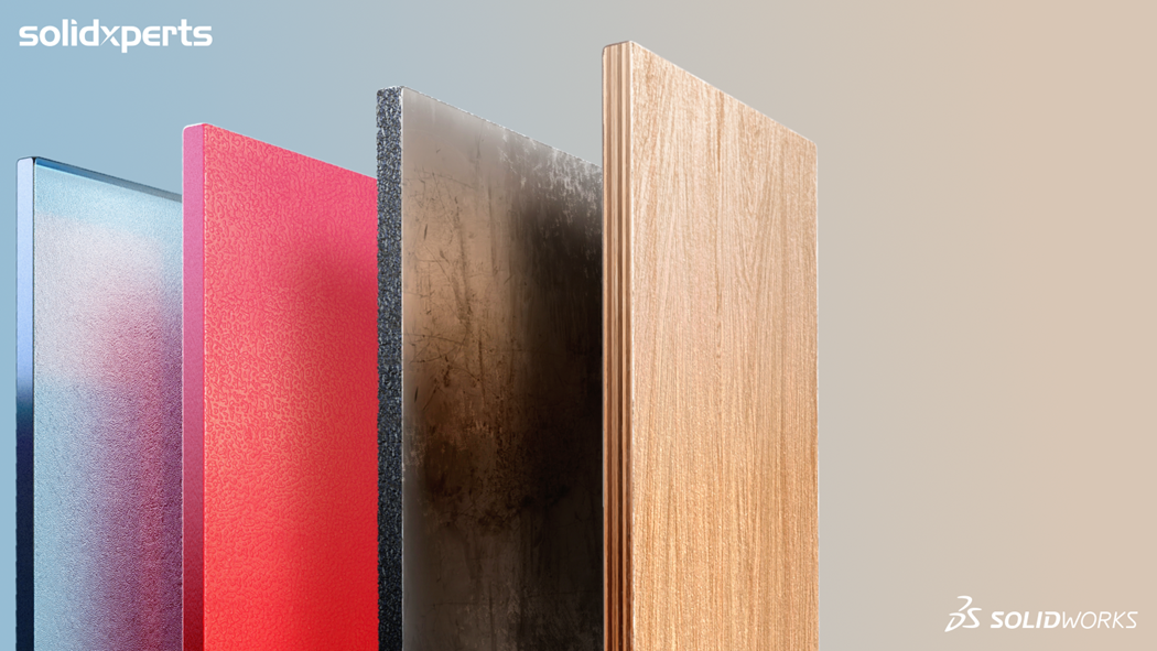
          As shown above, PBR materials allow you to generate all kinds of substances, such as wood, metal, plastic, glass, and more. There’s no need to constantly switch material types—just a few parameter changes are enough.

          Materials vs. Textures: What’s the Difference?

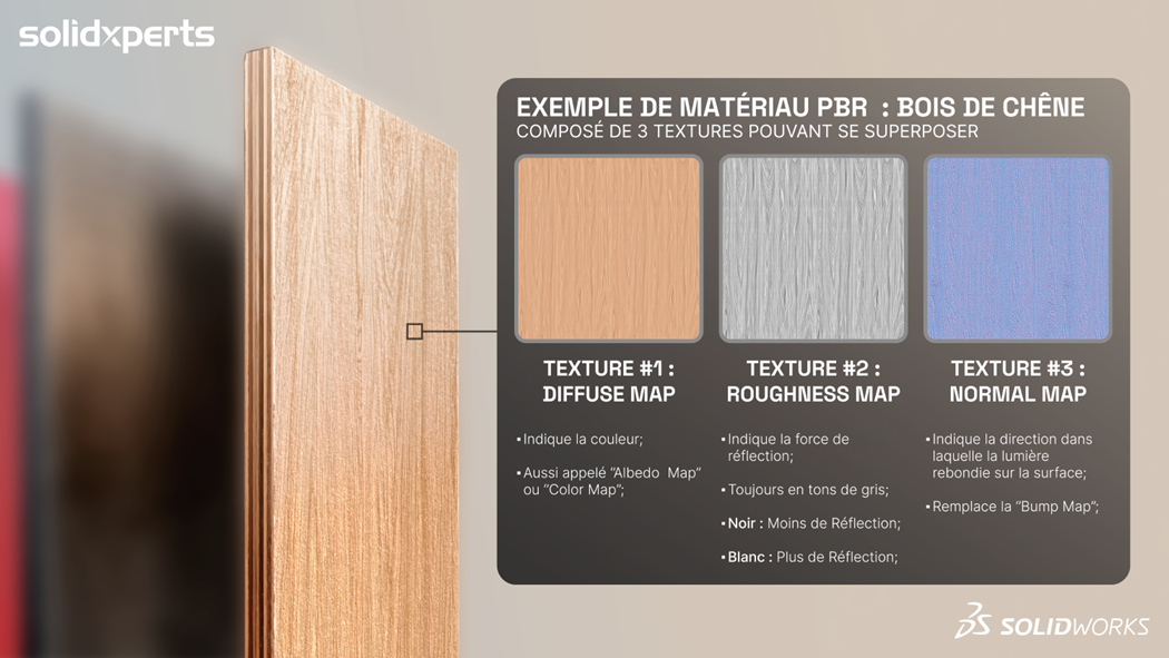
          New users of PBR materials often wonder why more than one texture is needed to create a single material. A photo of wood texture alone is not enough to tell rendering software how the material should behave.

          For something as basic as a wood material, you will likely need at least two or three textures to achieve a realistic result. The good news is that you do not have to create these textures yourself. Many PBR texture packs are available online. These texture sets are designed to be layered over your model to produce the desired effect.

          Often, texture packs include more textures than you will actually need in SOLIDWORKS Visualize. That is because each rendering engine may use a different number of texture maps to achieve the same result. In Visualize, you can often create realistic materials using just Diffuse and Roughness textures.

          Examples of PBR Materials in SOLIDWORKS Visualize

          It is important to use stackable textures (from the same family or originating from the same substance) so that the different types of information they generate remain consistent with one another.

          My PBR Materials Don’t Look Right…

          Now that you are using PBR materials, how do you make sure they stand out? Sometimes the materials are correctly set up, but the lighting, model, or scene fails to showcase their strengths.

          It is not enough to configure PBR materials properly. Your rendering environment also needs to support and highlight their details. This is where post-processing becomes essential.

          Don’t Expect Final Results in the Viewport!

          Do not worry if the real-time preview in the SOLIDWORKS Visualize viewport does not look perfect. Like all rendering engines, Visualize depends on post-processing software such as Photoshop or After Effects to enhance the final image.

          In fact, it is normal and often necessary to use post-production tools to bring out the fine details in your render. Visualize cannot generate all the visual information in a single image.

          Try Render Passes!

          When rendering a scene, the goal is not to get the final result in the viewport. Instead, the objective is to load your scene with as much visual data as possible through materials, textures, lighting, and more.

          All of this data cannot be shown effectively in a single image. This is why render passes exist.

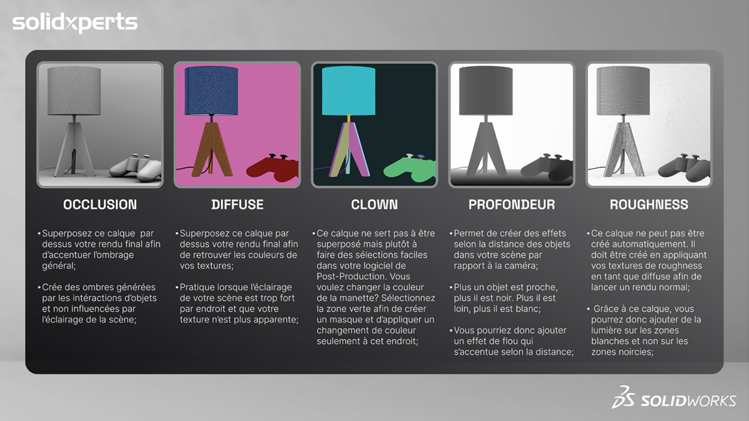
          This is not an issue unique to SOLIDWORKS Visualize. Most rendering engines cannot produce one image that contains everything you need. Render passes divide your render into multiple images, each representing a different visual component of the scene.

          PBR materials become especially useful in this process, as they contain more embedded data. This extra information is saved in the render passes and can be layered in post-production software to fine-tune your image.

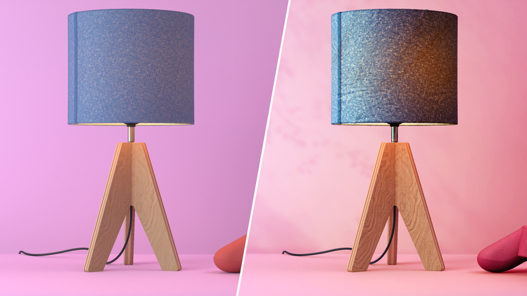
          Without Layers and With Layers after SOLIDWORKS Visualize

          On the left, the raw render as produced in Visualize without using render passes. On the right, the same render, procedurally enhanced in Photoshop by applying the different layers generated by SOLIDWORKS Visualize.

          Choose a Procedural Post-Production Workflow

          Post-production software like Photoshop can be complex to learn. That’s why you should adopt a procedural workflow that relies not on your team’s artistic skills, but on predefined parameters.

          When incorporating your render passes into your post-production software, avoid editing the image using brushes or other destructive methods. Instead, use layer blending and masks to follow a workflow that delivers consistent results. This approach is not only easy to adjust, but also easy to teach to the rest of your team.

          There’s no need to draw, paint, or create special effects—your render layers already contain all the information you need to produce a final image that matches your vision (see image below).

          Generate Images in Photoshop After SOLIDWORKS Visualize

          It’s Now your Turn to Make Your SOLIDWORKS Visualize Renders Stand Out!

          Your project deserves to shine in SOLIDWORKS Visualize. By applying modeling best practices, using the power of PBR materials, and enhancing your images through post-production, you are now equipped to create renders that effectively communicate your design vision.

          With some experience, you will be able to showcase every visual detail and deliver final images that are clear, realistic, and impactful.

          If you have more questions, our SOLIDWORKS Visualize experts are here to support you in optimizing your rendering process.


          Olivier Racicot, expert SOLIDWORKS Visualize

          Olivier Racicot

          Software Instructor, CSWE

          X_green_halo

          Any questions? Need help? Ask one of our experts.

          Whether you’re ready to get started or just have a few more questions, you can contact us toll-free:

            How to Reduce Costs in Your Designs with Topology Optimization in SOLIDWORKS

            BLOG

            How to Reduce Costs in Your Designs with Topology Optimization in SOLIDWORKS

            [techtips_featured_image_shortcode]

            In design and engineering, striking the right balance between performance, material usage, and cost is crucial. Whether you’re working on parts for an automotive application, aerospace components, or even consumer products, the goal is often to create designs that perform optimally while using as little material as possible. This is where topology optimization in SOLIDWORKS comes into play. It’s a technique that helps you determine the best way to distribute material across your design to meet your performance goals. Various tools from Dassault Systèmes, such as SOLIDWORKS Simulation Premium and SOLIDWORKS Simulation Professional, can help guide you in making your parts more efficient and cost-effective. SIMULIA, a brand of other solutions from Dassault Systèmes, also supports topology optimization for more advanced simulation needs.

            In this tech tip, we’ll walk through what topology optimization is and how it works. We’ll also explore how it can help you design lighter, stronger, and more cost-efficient parts using a variety of simulation tools.

            What Is Topology Optimization?

            At its core, topology optimization is all about optimizing the material layout of a part to achieve specific performance goals. Imagine it like sculpting a piece of clay. Removing unnecessary material and shaping the remaining material in a way that ensures the part performs as required, without excess weight or material.

            Although the term “topology” might seem technical, it really just refers to how material is arranged within a given design space. In simple terms, topology optimization in SOLIDWORKS helps you design parts that are as efficient as possible by strategically placing material where it’s needed most. The end result is a part that’s lighter, more durable, and better suited to its intended function.

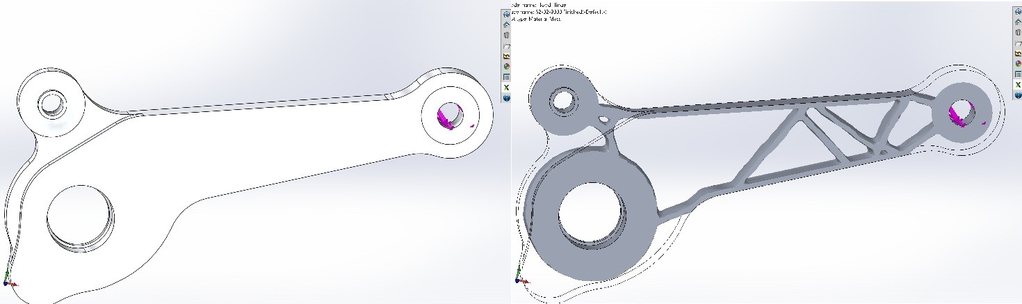
            Before and after topology optimization

            Key Objectives and Constraints of Topology Optimization

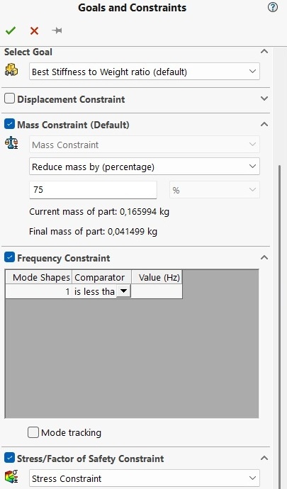
            When you set up a topology optimization study in simulation software, you’re essentially telling the software what you want to achieve. Some of the key objectives or constraints typically include:

            • Stress: Ensuring that the part can handle forces without failure. The goal is to have the material placed exactly where it’s needed to support the stresses applied to the part.
            • Factor of Safety: This is a cushion of extra strength that guarantees the part can withstand unforeseen or extreme conditions, minimizing the risk of failure.
            • Frequency: For parts exposed to vibrations, such as frames or supports, optimizing for frequency is essential. It helps ensure the part avoids resonating at certain frequencies, which could otherwise lead to failure.
            • Manufacturability: No matter how efficient a design is, it still has to be manufacturable. Simulation tools factor in real-world constraints during the design process. This ensures the final design can be produced using methods like CNC machining, additive manufacturing, or injection molding.

            Goals and constraints in a Topology Optimization in SOLIDWORKS Simulation

            How Does Topology Optimization Work?

            The process of running a topology optimization in a SOLIDWORKS study is straightforward. This holds true whether you’re using SOLIDWORKS Simulation Premium, SOLIDWORKS Simulation Professional, or other solutions from Dassault Systèmes. Here’s a simplified step-by-step guide:

            1. Define the Design Space: First, you outline the area in which material can be placed or removed. This is the region where you will optimize the design.
            2. Apply Loads and Fixtures: You then define the forces, pressures, and any constraints the part will experience in the real world. For instance, you might specify areas where the part is fixed or under load.
            3. Set Your Optimization Goals: Next, you specify what you want to achieve with the optimization. Are you focusing on reducing weight? Improving strength? Or perhaps increasing the safety margin? Simulation tools let you set multiple objectives at once.
            4. Run the Simulation: Once all parameters are in place, the software runs the simulation. It gradually removes material from areas that don’t contribute significantly to performance, leaving behind only the necessary structure.
            5. Evaluate and Refine the Design: After the optimization process is complete, you receive a design that meets your performance requirements. You can then further refine it to ensure it fits your specific manufacturing processes.

            Why Should You Use Topology Optimization?

            Here are some compelling reasons to incorporate topology optimization in SOLIDWORKS into your design process:

            1. Material Efficiency: By using topology optimization, you ensure that you’re only using as much material as necessary, creating parts that are lighter and more efficient. This is particularly important in industries like aerospace or automotive, where every gram saved can lead to better performance.
            2. Cost Reduction: Using less material translates to direct cost savings. Topology optimization can help lower both material costs and manufacturing expenses, as lighter parts are often easier and less expensive to produce.
            3. Enhanced Performance: By strategically placing material where it’s needed most, topology optimization ensures that your design is as strong as possible without adding extra weight or material. This results in better-performing parts overall.
            4. Faster Design Process: Instead of manually exploring different design options, simulation tools allow you to quickly run multiple simulations and find the best solution. This saves you time and effort during the design phase.
            5. Real-World Manufacturability: Simulation tools don’t just optimize for performance. They also keep manufacturability in mind. Whether you’re using 3D printing, traditional machining, or injection molding, the software ensures your optimized design can be made with real-world methods.

            Real-World Applications

            Here are a few examples of industries that benefit from topology optimization in SOLIDWORKS include:

            • Aerospace: Lighter, optimized parts are crucial for improving fuel efficiency and reducing the weight of aircraft. Engineers use topology optimization to design components that meet both performance and weight goals.
            • Automotive: In the automotive industry, optimizing parts for weight without compromising on safety and durability is key to reducing fuel consumption and production costs.
            • Consumer Products: From smartphones to sporting equipment, topology optimization helps designers create products that are both strong and lightweight, offering improved performance and better user experience.
            • Medical Devices: In medical fields, especially with implants or prosthetics, topology optimization can help create designs that are comfortable, effective, and use less material without compromising performance.

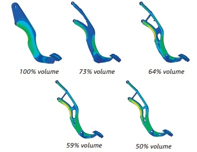
            Progression of topology optimization in SOLIDWORKS

            This nonlinear brake pedal example shows the progression of topology optimization as it attempts to maximize the stiffness while reducing the volume by 50% during 31 design cycles. Source: https://www.3ds.com/fileadmin/PRODUCTS-SERVICES/SIMULIA/RESOURCES/SIMULIA-Abaqus-Topology-Optimization-Module.pdf

            A Brief Look at Generative Design

            While topology optimization is a reliable and proven method for optimizing designs, generative design is a more recent approach that can take things a step further. Generative design uses powerful algorithms to create multiple design alternatives based on a set of input parameters. It not only optimizes material layout but also explores entirely new shapes and forms that might not be immediately apparent.

            For example, generative design might suggest unusual geometries or structures, often resulting in designs that are lighter and more efficient than what traditional design approaches might produce. This is especially useful when working with complex shapes or materials that benefit from additive manufacturing (3D printing).

            While generative design is a cutting-edge technology, topology optimization remains a great starting point. It allows for the creation of structurally optimized components that meet performance goals while adhering to manufacturing constraints.

            Engineering the Future: Unlock Efficiency and Savings with Topology Optimization in SOLIDWORKS

            Whether you’re using SOLIDWORKS Simulation Premium, SOLIDWORKS Simulation Professional, or other advanced simulation tools, topology optimization can transform your design process. It’s a game-changer for creating more efficient and cost-effective parts. By optimizing material usage based on specific design goals, you can create parts that perform better while using less material. Whether you’re looking to reduce weight, improve strength, or save on manufacturing costs, topology optimization can help you achieve all of these objectives.

            If you’re interested in exploring even more innovative possibilities, generative design offers a fascinating, forward-thinking approach. It builds on the foundation of optimization to explore new and creative solutions.

            By integrating topology optimization into your design process, you’ll not only improve your product’s performance but also save time and money. This leads to designs that are both more efficient and manufacturing-ready.

            This series of short videos shows you how to set up a topology optimization study using SOLIDWORKS Simulation to help you reach your goals. Want to go further? Contact our experts to get training or learn more about SOLIDWORKS Simulation.


            Chung Ping Lu, eng.

            Chung Ping Lu, eng.

            Senior Technical Representative

            X_green_halo

            Any questions? Need help? Ask one of our experts.

            Whether you’re ready to get started or just have a few more questions, you can contact us toll-free:
              SOLIDWORKS Biomedical Applications are Shaping the Future of Medecine

              BLOG

              SOLIDWORKS Biomedical Applications are Shaping the Future of Medecine

              [techtips_featured_image_shortcode]

              Biomaterial Modelling with SOLIDWORKS

              Biomaterial modeling with SOLIDWORKS has evolved into a powerful tool for various biomedical applications, including the production of custom 3D anatomical models, medical implants, and scaffolds. It enhances the design and fabrication process for biomaterials used in dental, medical, and biomedical engineering by offering precision, customization, and integration with 3D printing.

              What Are Biomaterials?

              Biomaterials are special materials designed to interact with the living systems of the human body. They can be natural or synthetic, and they are used to repair, replace, or support damaged tissues and organs.

              They are fabricated from various materials that interact safely with the body, such as metals, ceramics, plastics, and tissues. Some of these materials are degradable and can be absorbed by the body over time as our body already contains particles of materials like magnesium and iron. Others are non-degradable, such as titanium and chromium, and will remain permanently in the body.

              Imagine materials that can mimic bones, heal wounds, or even deliver medicine right where it’s needed. That’s the power of biomaterials!

              Where Are Biomaterials Used?

              Biomaterials are used in many lifesaving and life-enhancing fields, such as:

              • Medicine: Artificial joints, heart valves, dental implants
              • Tissue Engineering: Scaffolds that help grow new skin, bones, or cartilage
              • Drug Delivery: Tiny devices that release medicine slowly inside the body
              • Diagnostics: Sensors that detect diseases at early stages

              Why Are Biomaterials Important?

              Biomaterials are revolutionizing healthcare by making treatments more effective, safer, and personalized.

              • They help people walk again with implants
              • They enable faster healing with smart bandages
              • They help people live longer with advanced medical devices

              In the future, biomaterials will play an even bigger role in improving quality of life and solving medical challenges.

              Biomaterials bring together biology, engineering, and innovation to heal and improve human lives. They are truly materials for a better and safer future.

              Exploring Biomedical Modeling Capabilities in SOLIDWORKS

              SolidWorks helps engineers and designers create 3D models of objects before manufacturing them.

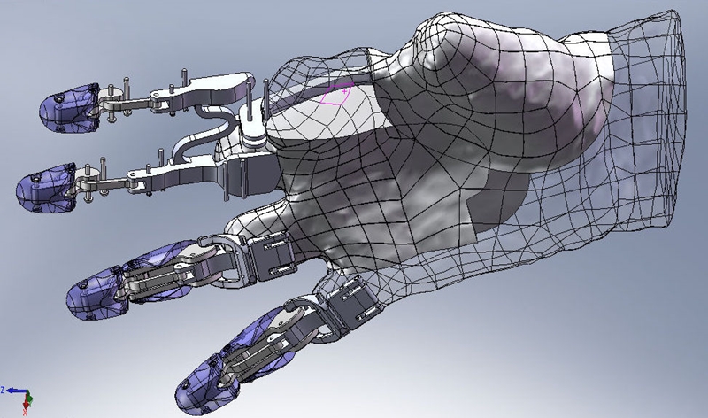
              SolidWorks Biomedical Innovation - Hand 3D modelling

              When it comes to biomaterials, SOLIDWORKS is essential because it makes designing medical devices and implants faster, easier, and more accurate.

              Moreover, it makes biomaterials design smart, efficient, and innovative, helping doctors and engineers create life-changing medical devices that improve and save lives.

              How Medical Device Design Enhances Patient-Specific Solutions?

              1. Bringing Ideas to Life in 3D

              Imagine a doctor needs a special bone implant for a patient. With SOLIDWORKS, we can design the exact shape and size of the implant on the computer, just like building something in 3D, before making it. This ensures better fit and comfort for the patient, making dreams come true.

              2. Testing Before Making

              SOLIDWORKS lets us simulate how strong and safe the biomaterial design is. For example, checking if an artificial joint can handle walking, running, or lifting. This helps avoid mistakes and ensures the device won’t fail inside the body.

              3. Saving Time and Money

              Instead of making many physical prototypes to test, we can test and improve designs on the computer. This makes the whole process faster and more cost-effective, bringing new medical solutions to patients quickly.

              4. Easy to Make with 3D Printing

              Once we finish designing biomaterials in SOLIDWORKS, we can send the design to a 3D printer and manufacture it using biocompatible materials. This is ideal for custom-made implants like dental pieces, bone scaffolds, and prosthetics.

              SolidWorks Biomedical Innovation

              Role of SOLIDWORKS in Biomaterials Design and Fabrication

              1. 3D Modeling of Biomedical Implants and Devices

              SOLIDWORKS offers advanced 3D modeling tools that allow engineers and researchers to create precise models of medical implants, prosthetics, and tissue scaffolds. Its parametric design feature enables easy modifications and iterations, which is critical for designing customized implants tailored to individual patients, such as orthopedic implants and dental prosthetics.

              By using patient-specific data from CT or MRI scans, SOLIDWORKS can generate highly accurate models that ensure better fit and functionality.

              2. Simulation and Analysis of Biomaterial Properties

              SOLIDWORKS includes powerful tools like SOLIDWORKS Simulation and SOLIDWORKS Flow Simulation to analyze mechanical properties such as:

              • Stress and strain distribution
              • Fatigue life prediction
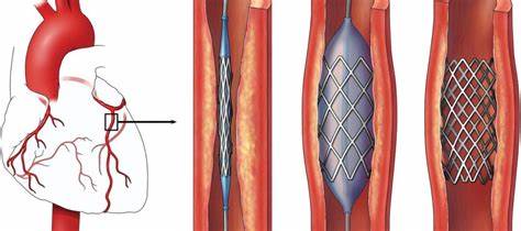
              • Thermal and fluid flow analysis (e.g., blood flow in vascular implants)

              These simulations are crucial to ensure biomaterials withstand physiological loads and perform effectively under real-life conditions. Simulating these scenarios reduces risks, time, and cost.

              3. Topology Optimization for Lightweight and Strong Structures

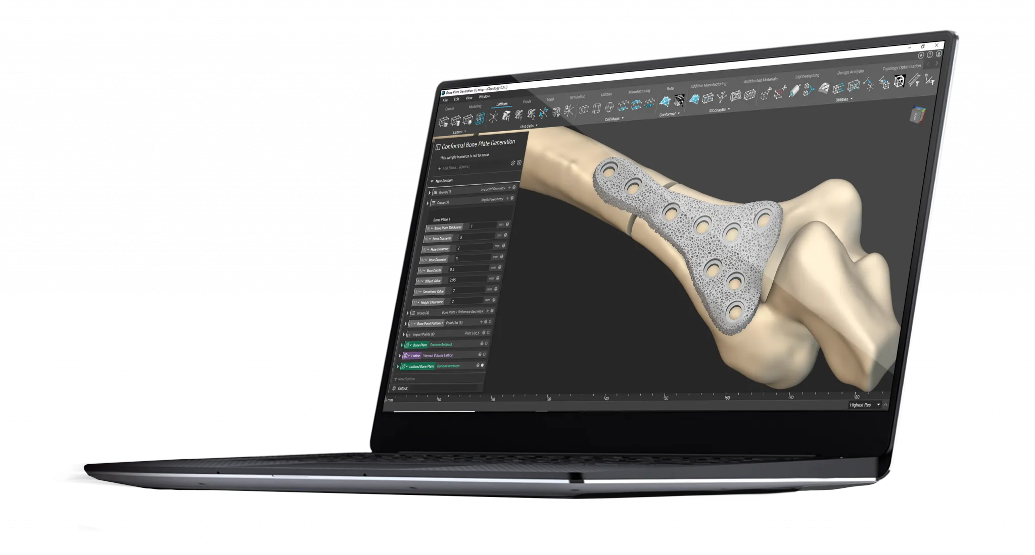
              In orthopedic and dental fields, biomaterials must be lightweight yet strong. SOLIDWORKS’ topology optimization tools enable the creation of lattice and porous structures, essential for bone scaffolds that promote tissue growth while maintaining strength.

              These optimized designs mimic natural bone architecture, ensuring biocompatibility and successful integration.

              4. Integration with Additive Manufacturing (3D Printing)

              Many biomaterial devices are fabricated using 3D printing technologies. SOLIDWORKS supports export formats (e.g., STL) compatible with 3D printers, allowing direct fabrication of complex geometries with biocompatible materials like titanium alloys, biodegradable polymers, and hydrogels.

              This integration accelerates prototyping and production, supporting rapid innovation in biomedical engineering.

              Linking 3D Scans to SOLIDWORKS

              Linking 3D scans to SOIDWORKS is critical in biomaterial applications for several reasons:

              1. Enhanced Design Accuracy

              • Precise Anatomical Models: 3D scans offer highly accurate anatomical representations, directly imported into SOLIDWORKS for perfectly fitted medical devices.
              • Detailed Surface Modeling: SOLIDWORKS’ ScanTo3D functionality converts scanned data into detailed surface models, essential for complex biomaterial designs.

              2. Streamlined Workflow

              • Efficient Data Integration: Seamless integration of 3D scans into SOLIDWORKS reduces manual effort and time.
              • Automated Processes: Tools like Mesh Prep Wizard and Surface Wizard automate scan-to-CAD conversion, enhancing productivity.

              3. Improved Collaboration

              • Shared Data: Easy sharing of accurate data fosters collaboration among engineers, designers, and medical professionals.
              • Documentation and Communication: SOLIDWORKS helps create comprehensive documentation, simplifying communication of design intent.

              4. Benefits for Doctors and Patients

              • Customized Medical Devices: Doctors can design custom-fit implants and prosthetics with higher precision and lower error rates.
              • Enhanced Surgical Planning: Accurate 3D models allow for better pre-surgical planning, reducing risks and improving patient outcomes.

              The Impact of SOLIDWORKS Biomedical Solutions on the Future of Healthcare

              In conclusion, SOLIDWOKRS biomedical applications are revolutionizing the healthcare landscape. By empowering engineers, researchers, and clinicians to design, test, and manufacture complex medical devices and biomaterial structures, SOLIDWORKS enables the creation of safe, effective, and patient-specific solutions.

              Whether it’s simulating bone implants, developing tissue scaffolds, or customizing drug delivery devices, SOLIDWORKS biomedical technology plays a vital role in enhancing human health. With continued advancements, SOLIDWORKS will remain at the forefront of biomaterial innovation, bridging engineering and medicine to improve lives globally.

              To explore how SOLIDWORKS biomedical solutions can support your next medical innovation, contact our experts today for guidance and collaboration.

              X_green_halo

              Any questions? Need help? Ask one of our experts.

              Whether you’re ready to get started or just have a few more questions, you can contact us toll-free:
                Getting Started with DriveWorks Automation

                BLOG

                Getting Started with DriveWorks Automation

                [techtips_featured_image_shortcode]

                In today’s busy manufacturing world, getting custom products out fast and right is very important. Design automation can help you achieve this. It saves time, cuts down on mistakes, and lets engineers focus on more valuable tasks.

                If you are new to automation or thinking about using it in your design process, this guide will help. It will cover the fundamentals and advantages of DriveWorks automation within SOLIDWORKS.

                What is Design Automation?

                Design automation is a method of automating repetitive design tasks in CAD systems. Rather than creating different models for a product by hand, automation lets you set up your designs using rules, logic, and specific inputs.

                With DriveWorks, you can make SOLIDWORKS parts, assemblies, and drawings automatic. This leads to faster results, better consistency, and fewer delays.

                Who Can Benefit from DriveWorks Automation?

                If your team frequently:

                • Makes custom adjustments to your product
                • Re-designs similar SOLIDWORKS models with small changes.
                • Has long wait times because of the engineering workload.

                …then design automation is a great fit for you.

                It is exceptionally useful for companies that delivers products that can be changed or set up differently to the needs of their clients. This includes products like conveyors, cabinets, doors, machinery, grain silos, staircases, truck trailers and more!

                Why Design Automation Matters in Custom Manufacturing

                In custom manufacturing, each project has its own unique requirements. Providing custom solutions can help you stand out from the competition. However, it also makes things harder. You may need more design hours. There is a higher risk of mistakes leading to deadlines not being met.

                This is where design automation becomes essential.

                • Consistency Without Compromise: Automation uses rules every time. This ensures that each version meets engineering standards and customer needs. It helps avoid mistakes and lowers the chance of expensive errors.
                • Speed from Quote to Manufacturing: Automated design processes quickly reduce the time needed for tasks. What once took hours can now be done in minutes. This gives your customers quotes faster and shortens the time to market.
                • Scaling Customization: You don’t have to manually manage every product version anymore. With automation, you can grow your offerings without adding extra work for engineers. This makes mass customization easy and profitable.
                • Empowering Your Team: Engineers can focus on more important work, like product development and new ideas. At the same time, sales teams can create quotes and visuals using web-based configurators—integrated into your workflow and accessible to both engineers and sales for real-time collaboration.

                What Can You Automate with DriveWorks?

                With the right setup, you can automate:

                • Dimensions and Geometry in 3D models
                • Features, Instances and Property as metadata
                • Drawings, including views, datacards, and BOMs, and notes.
                • Documents like quotes, cover letters, datasheets, and emails
                • Outputs such as DXFs, PDFs, and STL files

                This means there will be less hands-on work, fewer mistakes, and more time saved in your organization.

                How to Get Started

                1. Find repetitive tasks: Look at where your team spends a lot of time on repetitive tasks in SOLIDWORKS.
                2. Create rules and logic: Use DriveWorks to set up rules that explain how your designs should change based on input values.
                3. Test and improve: Begin with a small pilot project and slowly grow your automation.
                4. Grow and use: After testing, apply the automation to more product lines and connect it with quoting or CRM systems.

                Why DriveWorks automation?

                Design automation isn’t just about saving time. It’s about transforming the way your team works. Whether you’re automating a single product or building an entire online configurator, DriveWorks delivers more than just efficiency. It empowers smarter workflows, stronger collaboration, and scalable innovation across your business.

                Here are three key reasons why DriveWorks stands out:

                • Accelerate Design with Intelligent Automation: Say goodbye to repetitive tasks and hello to productivity. DriveWorks automates routine design processes which helps your team work faster, reduce manual errors, and focus on innovation.
                • Seamless Integration for a Smarter Workflow: Connect your favorite tools and systems, integrating effortlessly with Solidworks and PDM. DriveWorks can also integrate with other key softwares such as CRM and ERP’s, creating a streamlined automation pipeline that boosts efficiency across your entire operation.
                • Empower Collaboration Across Teams: Design thrives on collaboration, not isolation. DriveWorks fosters real-time collaboration between engineers, designers, and other departments such as sales and marketing. Share feedback, align goals, and keep projects moving forward—together.

                At Solidxperts, we support companies of all sizes in harnessing these capabilities with DriveWorks, delivering smoother engineering, greater accuracy, and faster sales cycles.

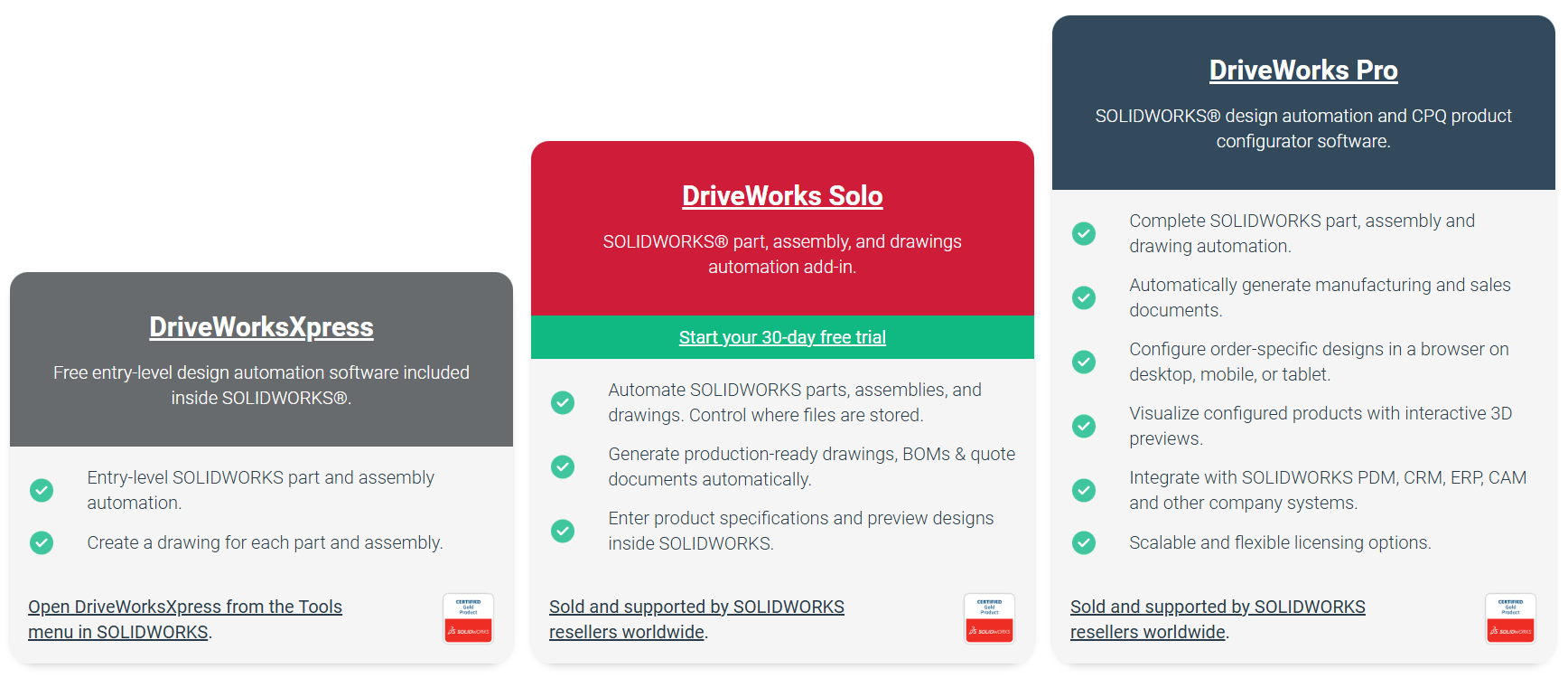
                DriveWorks Product Tiers: Xpress, Solo & Pro

                DriveWorks has three types of design automation tools. Each one is designed for different needs and sizes of businesses. Here’s a simple guide to help you find the best solution for you:

                DriveWorksXpress:  Entry-Level Automation (Free)

                • Comes with every SOLIDWORKS license
                • Helps to automate parts and assemblies
                • Perfect for automating tasks you do often
                • Can be found in the SOLIDWORKS Tools menu
                • A good starting point for small automation projects

                DriveWorks Solo: Advanced Automation for Engineers

                • Get a 30-day free trial
                • It automates parts, assemblies, and drawings.
                • Direct control over file naming and storage placement.
                • It creates drawings that are ready for production, along with BOMs and quote documents.
                • A built-in form designer helps you make custom input forms.
                • This is good for companies that want to improve their engineering efficiency.

                DriveWorks Pro: Comprehensive Automation & CPQ Solution

                • This system is modular and can grow to meet different business needs.
                • It allows for complete SOLIDWORKS automation and online 3D configuration.
                • It works well with CRM, ERP, and PDM systems.
                • You can configure it online from any device.
                • This solution is perfect for companies that want to link sales, engineering, and manufacturing processes.

                DriveWorks Tiers

                Need Help?

                Our certified DriveWorks experts at Solidxperts are here to assist you with your automation projects. We can help you with training, consultation, or complete implementation. Whatever you need, we are ready to support you.

                X_green_halo

                Any questions? Need help? Ask one of our experts.

                Whether you’re ready to get started or just have a few more questions, you can contact us toll-free:

                  Understanding Audit Trails in SOLIDWORKS PDM

                  BLOG

                  Understanding Audit Trails in SOLIDWORKS PDM

                  [techtips_featured_image_shortcode]

                  Designing products in SOLIDWORKS is one of the first steps in an R&D process. However, how can you meet the requirements of various certification bodies? Depending on your field of activity, you may need to comply with standards such as:

                  • FDA 21 CFR Part 11 (Regulations on electronic records and electronic signatures)
                  • ISO 9001 (Quality management systems)
                  • ISO 13485 (Quality management in the medical device industry)

                  A common requirement among these standards is the availability of an audit trail. SOLIDWORKS PDM already provides a history of your CAD file evolution, but did you know that it also offers tools for generating reliable and increasingly advanced audit trails?

                  What are the Challenges Related to Audit Trail Production in a PDM System for Certification Compliance?

                  The following concerns and challenges arise when implementing a Product Data Management (PDM) system while ensuring the presence of audit trails. Taking the previously mentioned standards as examples:

                  1. Integrity and Security of Audit Trails

                  To begin with, preventing modification or deletion of logs is essential. Audit trails must be immutable and shielded from unauthorized changes. This is a core requirement of 21 CFR Part 11 and ISO 9001/13485.

                  Moreover, access control and authentication are critical. Only authorized users should have access, and all actions must be timestamped.

                  2. Compliance with Regulatory Requirements

                  Traceability of modifications and approvals: Any modification to a document must be recorded with user identity, date, and justification, as per the standards.

                  PDM system validation: The document management software must be validated to ensure the integrity and reliability of records (21 CFR Part 11).

                  Archiving and retention of audit trails: Documents and their history must be securely stored and accessible in case of an audit (ISO 13485, FDA).

                  3. Performance and Data Management

                  Log volume and performance impact: Continuous activity logging can slow down the system, requiring optimization solutions.

                  Interoperability with other systems: The PDM must be compatible with other software (ERP, MES, LIMS) while ensuring compliance with regulations.

                  4. User Training and Awareness

                  Misuse of functionalities: Lack of training can lead to errors in audit trail recording.

                  Adapting to regulatory constraints: Compliance processes can be seen as restrictive and may require change management efforts.

                  In summary, implementing audit trails in a PDM system that complies with FDA 21 CFR Part 11, ISO 9001, and ISO 13485 requires rigorous access management, system validation, data security, and performance optimization. Striking a balance between regulatory compliance and usability is crucial to ensuring effective adoption by teams.

                  Audit Trails in SOLIDWORKS PDM

                  Document History

                  Each document has a history of its evolution. Recently, SOLIDWORKS PDM has recently added more details regarding document access, particularly check-out operations. Document approval details are also stored in this history and can be considered electronic signatures.

                  System History in SOLIDWORKS PDM Administration

                  To ensure the integrity of SOLIDWORKS PDM configurations, a system history log is available. This allows auditors to track system changes, with recorded dates and users responsible for modifications.

                  File Access in SOLIDWORKS PDM

                  One of the most critical audit trails for security is tracking who accessed specific documents and when. SOLIDWORKS PDM has recently added the capability to log all file access activities, consolidating all operations into a single audit file.

                  SOLIDWORKS PDM Access Logs

                  Recently added to SOLIDWORKS PDM audit trails is a log of user login and logout activities. These logs include user connections, workstation details, IP addresses, applications used, and even connections from external systems.

                  SOLIDWORKS PDM Archive Server Activity Log

                  SOLIDWORKS PDM compiles archive server activities into a log file. If system errors occur, they are recorded in this log, making it an essential tool for error analysis and troubleshooting.

                  SOLIDWORKS PDM Client Log File

                  Each SOLIDWORKS PDM client collects information in a log file, recording communication errors, connections, and disconnections.

                  Key Takeaway: Audit Trails in SOLIDWORKS PDM as a Pillar of Regulatory Readiness

                  Audit trail management is a key factor in ensuring compliance with regulatory standards such as FDA 21 CFR Part 11, ISO 9001, and ISO 13485. SOLIDWORKS PDM provides a comprehensive set of tools to ensure data traceability, integrity, and security. With advanced features like document history, access logs, connection tracking, and server/client logs, transparency and regulatory compliance become easier to maintain.

                  By adopting these tools, companies can enhance quality control, streamline audits, and meet the strict requirements of certification bodies. However, to fully leverage these capabilities, access management must be optimized, systems must be validated, and users must be properly trained. By combining rigor, security, and efficiency, SOLIDWORKS PDM becomes a major asset for compliant and efficient engineering data management.

                  References

                  ISO 9001 – Retrieved from: https://www.iso.org/standard/62085.html

                  FDA 21 CFR Part 11 – Retrieved from: https://www.ecfr.gov/current/title-21/chapter-I/subchapter-A/part-11

                  ISO 13485 – Retrieved from: https://www.iso.org/standard/59752.html

                  X_green_halo

                  Any questions? Need help? Ask one of our experts.

                  Whether you’re ready to get started or just have a few more questions, you can contact us toll-free:

                    Use SOLIDWORKS Certifications to Stand Out to Recruiters

                    BLOG

                    Use SOLIDWORKS Certifications to Stand Out to Recruiters

                    [techtips_featured_image_shortcode]

                    Have you been using SOLIDWORKS for years and want your skills to be recognized accordingly? Earning SOLIDWORKS certifications validates your expertise and can potentially open new career opportunities. Moreover, if you have a SOLIDWORKS license with an annual subscription, these certifications are free.

                    Why Obtain SOLIDWORKS Certifications?

                    As a recruiter within the team of SOLIDWORKS specialists at Solidxperts, I pay special attention to these qualifications when reviewing applications. Certified candidates are the first ones I contact when I have a position to fill. A few years ago, I received over 75 applications for a position, and my primary selection criterion was the CSWP certification. Standing out in the job market is just one benefit. Here are several other compelling reasons to pursue SOLIDWORKS certification:

                    • Professional recognition: They are highly respected in the industry and provide tangible proof of your skills.
                    • Skills validation: They confirm your mastery of SOLIDWORKS, a valuable asset for reassuring potential employers.
                    • Increased visibility: Displaying your credentials on your LinkedIn profile enhances your chances of being noticed by recruiters.
                    • Access to more qualified positions: Some companies require specific certifications for advanced roles.
                    • Proof of professional commitment: Obtaining certification demonstrates your willingness to improve and keep up with evolving technologies.

                    How to Obtain Your Certification for Free

                    Before diving into how to prepare, it’s worth knowing that certification exams are free if you have an active SOLIDWORKS subscription. Visit SOLIDWORKS Certification Subscription Services Offer for more info on eligibility and sign-up steps.

                    Skills Assessed in SOLIDWORKS Certifications

                    SOLIDWORKS certification exams are known to assess several key skills, including:

                    • Complex part and assembly design: Advanced use of 3D modeling tools.
                    • Configuration management: Creating and managing design variations within a single file.
                    • Stress analysis: Using simulation tools to evaluate design performance.
                    • Advanced feature utilization: Mastery of sheet metal, surfacing, and mold tools.
                    • Creating detailed drawings: Producing precise technical drawings with annotations and tolerances.

                    All certifications assess different skills. The CSWP (Certified SOLIDWORKS Professional) is one of the most recognized certifications. It demonstrates your ability to model complex parts and effectively assemble your designs. For practice, you can refer to this resource: CSWP Sample Exam.

                    As for the CSWE (Certified SOLIDWORKS Expert) is intended for seasoned users aiming for the highest level of SOLIDWORKS distinction. It represents advanced mastery and can even justify a salary increase. Learn more here: CSWE Certification Details.

                    In addition to CSWP and CSWE, several advanced certifications are available to further specialize your skills:

                    • CSWPA-SU (Certified SOLIDWORKS Professional – Surfacing)
                    • CSWPA-WD (Certified SOLIDWORKS Professional – Weldments)
                    • CSWPA-SM (Certified SOLIDWORKS Professional – Sheet Metal)
                    • CSWPA-DT (Certified SOLIDWORKS Professional – Drawing Tools)
                    • CSWPA-MT (Certified SOLIDWORKS Professional – Mold Tools)
                    • CSWPA-EP (Certified SOLIDWORKS Professional – Electrical Professional)

                    These certifications allow you to deepen your skills in specific areas and strengthen your technical expertise.

                    Tips for Succeeding in SOLIDWORKS Exams

                    To maximize your chances of success in SOLIDWORKS certification exams, here are some practical tips:

                    • Practice regularly: Familiarize yourself with the SOLIDWORKS interface and practice solving complex problems.
                    • Use official resources: Study guides and sample exams provided by SOLIDWORKS are invaluable for understanding the question format.
                    • Manage your time effectively: During the exam, start with the questions you are most confident in to save time.
                    • Master keyboard shortcuts: They can improve your speed and efficiency during modeling.
                    • Focus on key features: Exams often focus on essential skills such as sketches, assemblies, and drawings.

                    Recommended Learning Resources

                    To effectively prepare for SOLIDWORKS certifications, several resources are available:

                    • Official video tutorials: SOLIDWORKS offers detailed videos explaining key concepts and advanced techniques.
                    • Official study guides: These documents detail exam topics and provide practical exercises.
                    • Online forums and communities: Engaging with other candidates or certified professionals can offer valuable tips and insights.
                    • Training platforms: Sites like MySolidWorks offer online courses specifically designed for certification preparation.

                    Steps to Add a Credly Badge to Your LinkedIn Profile

                    By successfully completing a SOLIDWORKS certification, you can obtain a digital badge via the Credly platform. This badge provides a verifiable and shareable proof of your skills, which you can easily integrate into your LinkedIn profile, online resume, or email signatures. It enables recruiters and employers to quickly validate your skills and enhances your professional visibility. Note that the training you complete with Solidxperts will also grant you a Credly badge that you can display.

                    Learn more on our website: Solidxperts Credly Badges.

                    An Investment of Time, but a Worthwhile One 

                    Adding SOLIDWORKS certifications to your resume and LinkedIn profile is a strategic investment for your career. These credentials enhance your professional credibility, validate your technical skills, and increase your chances of being noticed by recruiters. If you have an annual subscription, don’t miss the chance to earn these valuable certifications for free. Reach out to Solidxperts today to start your preparation.

                    Certification Preparation with Solidxperts

                    To maximize your chances of success, Solidxperts offers training tailored to your needs. Whether you are a beginner or an advanced user, these courses will help you strengthen your knowledge and effectively prepare for certification exams. Our trainers have earned these qualifications themselves and are well-equipped to guide you to success. Explore the available course plans on Solidxperts Training page or simply contact us to plan customized training to suit your needs.


                    Martin Monarque

                    Technical Services Director

                    X_green_halo

                    Any questions? Need help? Ask one of our experts.

                    Whether you’re ready to get started or just have a few more questions, you can contact us toll-free:
                        Download

                          Download

                            Download