At Dassault Systèmes, keeping your account secure is a top priority. That’s why two-factor authentication (2FA) is now required when you access the DSx Client system.
What does this mean for you? In short: an extra layer of protection for sensitive data like user information and serial numbers. It also means a quick setup process the first time you log in and after that, peace of mind knowing your account is more secure.
This guide will walk you through:
How to set up 2FA on your phone (most common method).
How to set up 2FA on your computer using KeePassXC if you prefer not to use a mobile device.
Option 1: Setting Up 2FA on Your Phone
1. Download an Authenticator App
If you don’t already have one, install an authenticator app such as Google Authenticator, Microsoft Authenticator, or Okta.
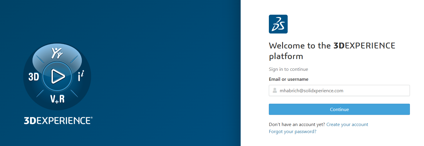
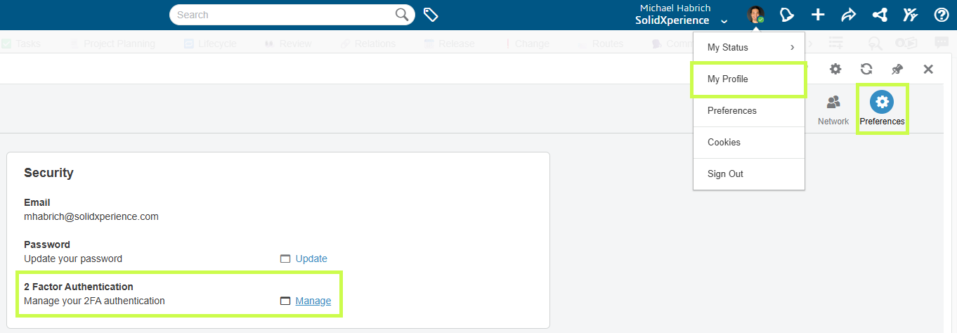
From your account, click My Profile > 2-Factor Authentication.
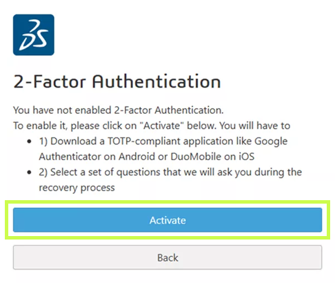
4. Activate 2FA
Select Activate to begin setup.
5. Set Recovery Options
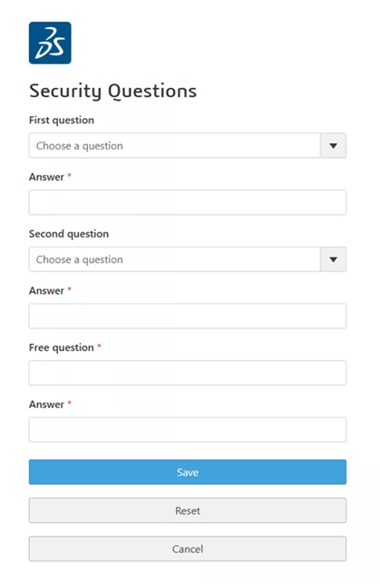
Answer the required security questions. These will be used if you ever lose access to your 2FA device.
6. Connect Your Authenticator
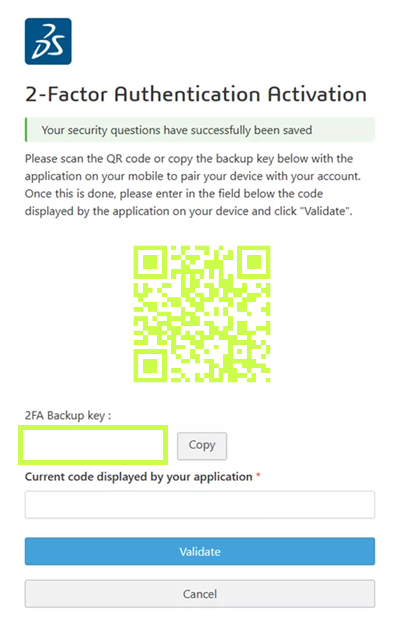
In your authenticator app, choose Scan a QR Code (or Enter a setup key if your phone has no camera). Scan the code provided by Dassault Systèmes.
7. Test and Confirm
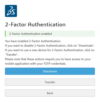
Your authenticator will display a 6-digit code. Enter it into DSx Client to confirm setup. Once successful, you’ll see a confirmation window — 2FA is now enabled! 🎉
Going forward: Every time you log into DSx Client, you’ll be asked for a code from your authenticator app.
Option 2: Setting Up 2FA on Your Computer (KeePassXC)
Prefer not to use your phone? No problem. You can configure 2FA directly on your computer with KeePassXC, a secure, open-source password manager.
1. Download and Install KeePassXC
Available for Windows, macOS, and Linux at KeePassXC’s website. Default installation options work fine.
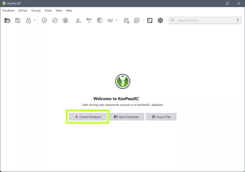
2.Create a Database
This is where your passwords and tokens are stored. Set a strong master password and keep it in a safe place.
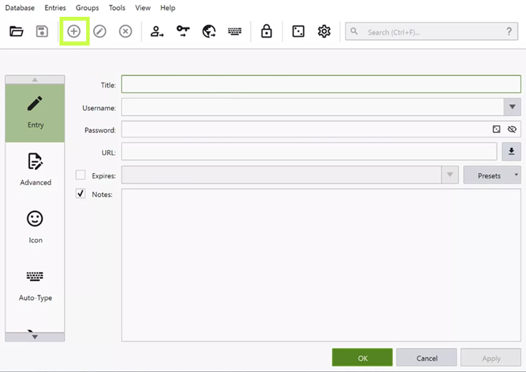
3.Add a DSx Client Entry
Create a new entry with:
Title: DSx Client
Username, Password
URL: https://dsxclient.3ds.com
4. Set Up the 2FA Key
Right-click your new entry > Setup TOTP. Enter the secret key provided in DSx Client (same as in the phone setup).
5. Test and Confirm
Click the clock icon next to your entry to generate a 6-digit code. Enter it in DSx Client. Once confirmed, your 2FA is ready to go.
Wrapping Up
That’s it! You’ve now secured your DSx Client account with two-factor authentication. Whether you chose to set it up on your phone or on your computer, you’re adding an important layer of protection to your Dassault Systèmes tools.
And remember, if you hit a bump along the way, the Solidxperts team is always here to help. Reach out to us, and we’ll make sure your account stays safe and your workflow stays smooth.
SOLIDWORKS PDM is a powerful tool for managing product data, but like any system, it is only as good as its implementation. Missteps in setup, usage, or governance can result in lost time, confused teams, or even corrupted data. Let’s break down the top five mistakes users and administrators make with SOLIDWORKS PDM and provide expert-backed solutions to fix them.
1. Don’t Let Permissions Kill Productivity
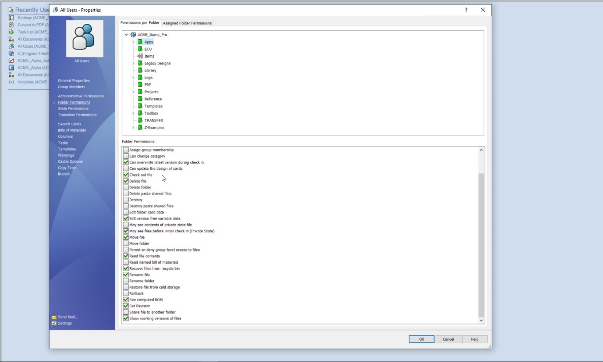
SOLIDWORKS PDM folder permissions tab, detailing access rights within the vault. The interface displays a folder tree and a checklist of enabled actions.
The Pitfall: Confusing or Dangerous Access Rights One of the most frequent and damaging mistakes in any PDM setup is mismanaging user permissions. When permissions are too strict, users waste time trying to access files or wait for someone with higher access to help. On the flip side, overly broad access can result in accidental overwrites, deletions, or unauthorized changes. For example, an engineer could accidentally releases a work-in-progress drawing because they were mistakenly given access to the “Released” state transition. This leads to procurement ordering incorrect parts based on an outdated design.
The Fix: Implement Role-Based Access Control (RBAC) Instead of managing individual user permissions, create user groups such as:
Designers
Engineers
Quality Control
Project Managers
Manufacturing
Assigning permissions at the group level simplifies administration but also ensures consistency. If someone’s role changes, you just move them between groups.
Best Practices:
Use the Permissions tool in PDM Admin to verify access levels
Restrict access to critical lifecycle transitions (e.g., “Approve,” “Release”)
Re-audit access rights quarterly, especially after organizational changes
Keep a changelog of all admin updates to permission groups
Why it matters:
Tight control over permissions protects data integrity, reduces user frustration, and limits the risk of human error.
2. Are Your Workflows Helping or Hindering?
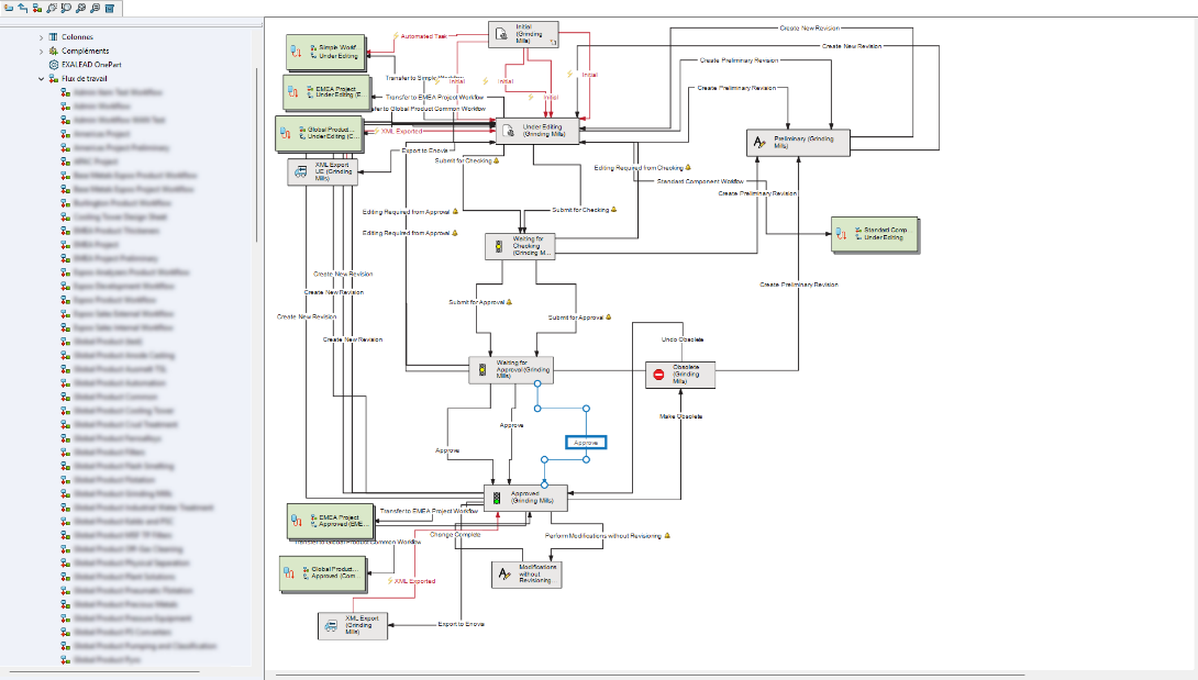
A highly detailed and customized SOLIDWORKS PDM workflow, illustrating the lifecycle of engineering files, workflows like this can introduce challenges in usability, maintenance, and onboarding, highlighting the importance of balancing control with simplicity in PDM design.
The Pitfall: Workflows That Don’t Reflect Real-Life Processes
Another common issue is poorly designed workflows. Often, workflows are either overly simplistic and fail to enforce proper checks or overly complicated, leading to user confusion and delays. For example, a workflow without a design review stage results in errors reaching production. Alternatively, a workflow with too many approval loops creates a bottleneck that delays time-to-market.
The Fix: Design Smart, Flexible Workflows
Good workflows reflect how your team actually works. Start by mapping out real-world processes on paper. Then replicate those with SolidWorks PDM using tools like:
Conditional Transitions
Automatic Status Changes
Notifications (via Dispatch or Task Add-ins)
Pro Tips:
Include mandatory review steps before “Release”
Create a sandbox or test vault to trial new workflows without disrupting production
Practice using screen recordings or internal guides to walk through common workflows. Even the best workflow cannot help if users don’t understand it.
3. Stop the Chaos: Fix Your Revision Control
The Pitfall: Manual File Naming and Confused Versioning
Few things frustrate engineers more than working on the wrong version of a file. Common issues include:
Duplicate files with suffixes like _final, _v2, _approved
Broken references from renamed assemblies
No clear revision history when questions arise
For example, a supplier receives an outdated drawing marked “FINAL_v3,” but the design team had already created “FINAL_v4” in a separate folder. Which results in countless dollars wasted and scrap material.
The Fix: Use PDM’s Automated Version and Revision Tools
SOLIDWORKS PDM is built to manage versions and revisions intelligently when used properly. By integrating revision control into your workflow transitions, you can track every change and automatically increment revisions when files pass certain gates such as “Approve.”
Steps to Implement:
Set up lifecycle states (e.g., Under Review → Approved → Released)
Configure transitions to increment revisions automatically
Use the built-in History tab to track who made what changes and when
Apply revision tables linked to metadata to eliminate manual edits on drawings
Important Tips:
Disable file renaming at the user level
Avoid copying files outside PDM to test changes; instead, use sandbox folders within the vault
Regularly purge obsolete versions to avoid clutter
Result:
Accurate, tamper-proof versioning builds trust across design, QA, and manufacturing teams.
4. Organize or Agonize: Clean Up That Vault
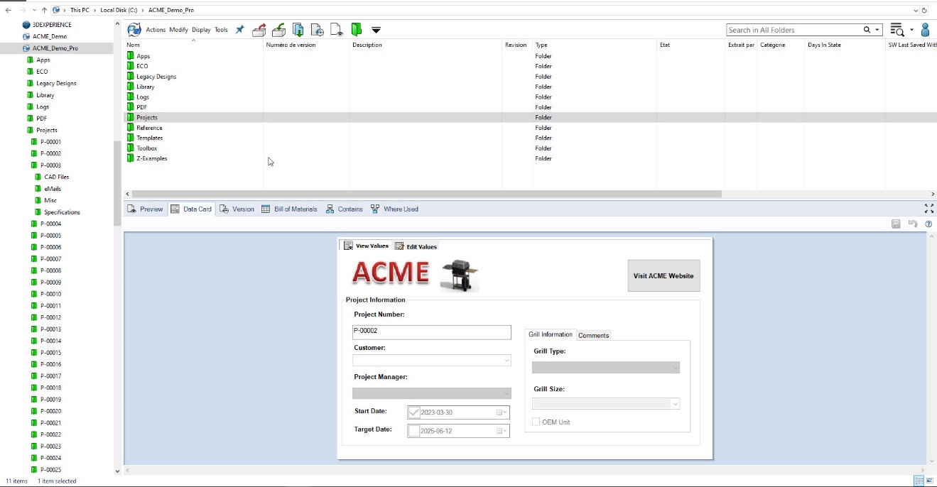
SOLIDWORKS PDM Vault interface, featuring a typical folder structure on the left and project metadata displayed in a custom data card below.
The Pitfall: Messy Folders, Inconsistent File Names, and Confusing Structures
Without naming conventions or a logical file system, even experienced users can spend hours hunting for the right file or, worse, use the wrong one.
For example, a project folder contains new_final, revA_drawing, Drawing1, and final_FINAL. No one knows which to use, and a new engineer duplicates the wrong one for a new design.
The Fix: Standardize File Naming and Folder Structures
Consistency is key to finding and managing data efficiently. Develop a file naming convention that reflects your project hierarchy and revision status.
Sample Naming Structure:
PRJ2025_ClampBracket_REV_B.SLDPRT
DWN1001_ClampBracket_REV_B.SLDDRW
Tips to Maintain Order:
Enforce naming rules with Data Cards
Use “Copy Tree” for project duplication to auto-rename and preserve links
Document your structure in an internal wiki or onboarding guide
Bonus:
Create folder templates tied to project types (e.g., Customer Jobs, R&D, Internal Use) to speed up setup and reduce human error.
5. One Crash Away: The Backup Plan You Wish You Had
The Pitfall: No Backup or Worse, Unusable Backups
It is easy to assume your IT team has your back until a vault crash or server failure proves otherwise. Even if backups exist, they may be incomplete, outdated, or impossible to restore. For example, your server crashes on a Friday night. IT discovers that the last backup was from three weeks ago and only covers the SQL database, not the archive files.
The Fix: Build a Complete, Tested Backup and Recovery Plan
A proper backup strategy must cover all components of SOLIDWORKS PDM:
SQL Database
Archive Server
Vault Settings (via the Admin tool)
Checklist for Backup Success:
Back up daily using Windows Task Scheduler or enterprise tools
Store backups off-site or in the cloud for disaster recovery
Simulate a full restore every quarter and document the steps
Disaster Recovery Plan Should Include:
Contact info for key stakeholders
Timeline for each recovery step
Inventory of hardware and software requirements
A change log for vault structure
Crucial Question:
If a critical client asks, “How quickly can you restore if the vault crashes?” do you have an answer you trust?
Bonus Mistake: Skipping Training and Internal Communication
Even the best-configured PDM system will not deliver value if users do not understand how to use it. Inconsistent user behavior leads to data quality issues, broken workflows, and user frustration.
Fix it with:
Scheduled team-wide PDM refresher sessions
A living document library of video walkthroughs and SOPs
Feedback loops such as a Slack or Teams channel for PDM issues
Pro Tip:
Use anonymous surveys to surface pain points or confusion that might not come up in meetings.
Stop Mistakes Before They Start
SOLIDWORKS PDM is not just a file storage system. It is the foundation of your product development lifecycle. Like any foundation, it requires care, structure, and proactive management. By recognizing and correcting the most common PDM mistakes, whether it is permissions, workflows, revisions, organization, or backup planning, you set your team up for success.
Takeaway Checklist:
Role-based permissions
Streamlined, mapped workflows
Automated revision control
Standardized file and folder naming
Complete, tested backup plan
Ongoing user training
Each of these practices improves traceability, compliance, and efficiency. Saving you time, money, and stress in the long run.
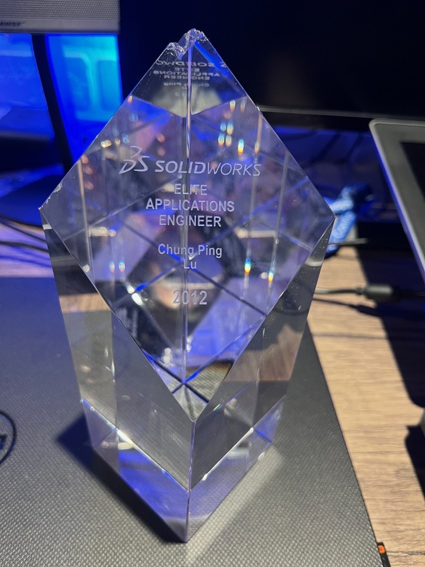
A few weeks ago, my SOLIDWORKS Elite Applications Engineer award fell, and the top part of it broke. I was both sad and frustrated. Sad because it meant something to me, and frustrated because I had placed it on a shelf that later tilted unexpectedly, sending everything crashing to the floor. Finding it broken on the ground that day was tough.
Accidents like this happen all the time. The products we design are also at risk of being dropped, so why not make them as resistant as possible?
That’s exactly where SOLIDWORKS Simulation drop tests come in.
In this guide, you’ll learn:
what a drop test is,
why drop test analysis is essential for product reliability,
and how to run a drop test in SOLIDWORKS Simulation step by step.
Why Drop Tests Matter for Product Design?
Any time a product is handled, shipped, carried, or installed, there’s a chance it could be dropped. A single impact can compromise safety, durability, performance, and sometimes even a company’s reputation.
Drop tests help engineers predict how their products will behave in real-world accident scenarios. Below are examples of industries where drop testing is essential to ensure reliability before manufacturing:
Consumer products & electronics
Industrial & heavy equipment
Medical devices
Sports equipment
Aerospace & aviation
Automotive & transportation
Military & defense
Packaging & logistics
Robotics & automation
Construction & civil engineering
Drop Test Prerequisites: What You Need Before Running a Simulation
Before running a drop test analysis, certain elements must be prepared. A 3D design is required to simulate the event digitally. Here are the steps:
Create the 3D model in SOLIDWORKS or import an existing geometry.
Apply materials (this step can also be performed directly in the study).
Simplify the model to reduce solving time (this may include suppressing non-critical parts or features).
How to Run a Drop Test Analysis in SOLIDWORKS Simulation
Once your model is ready, you can set up the drop test using the following steps:
Enable the SOLIDWORKS Simulation add-in.
Create a new Drop Test study.
Apply any missing material properties.
Define interactions if needed.
Set up the drop test conditions (drop height or impact velocity, orientation, ground parameters, etc.).
Adjust result options (duration after impact, saving options, etc.).
Mesh the model and run the analysis.
Interpreting Your Drop Test Results
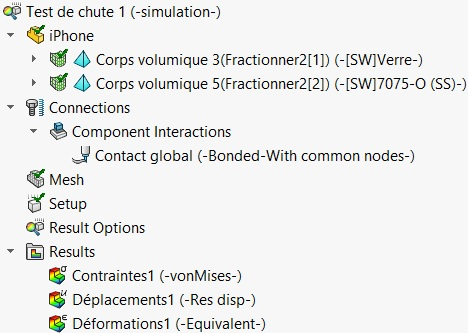
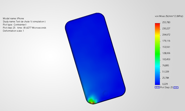
After running the analysis, several result types become available, such as stress and deformation plots. These help you determine whether the product will remain elastic, undergo plastic deformation, or potentially fail, and where such failures are likely to occur.
The example below shows the kind of output SOLIDWORKS Simulation provides once the calculations are complete:
Improving the Design Through Simulation
Thanks to the results, you can identify weak points where the product is likely to fail. You can then reinforce the design. For example, by adding fillets, increasing wall thickness, or selecting a stronger material.
Sometimes, results show that a part is overdesigned. In these cases, you may reduce thickness or remove unnecessary material to lower weight and cost. This is a key step in optimizing your product.
Simply make the changes and re-run the drop test to validate the improvements.
Bringing It All Together: Stronger Designs Through Simulation
With SOLIDWORKS Simulation, you can test your product digitally long before manufacturing it. A drop test is just one of many analysis types available to help you validate performance and reliability.
I initially blamed myself for the broken award, but maybe if the shelf had been designed to be stronger, the accident could have been avoided. Who knows?
From linear static to nonlinear dynamic analyses, SOLIDWORKS Simulation provides a complete suite of tools to help engineers validate their designs efficiently. At Solidxperts, we are committed to helping our customers achieve excellence in their engineering projects.
Looking to sharpen your skills? Browse our upcoming trainings, available at our offices or online. Whether you’re new to simulation or ready to deepen your expertise, our certified specialists are here to support you every step of the way.
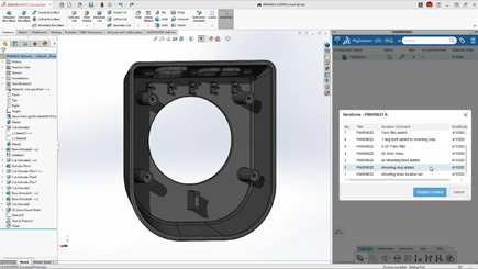
SOLIDWORKS 2026 delivers a wave of powerful enhancements designed to accelerate collaboration, streamline data management, and strengthen connectivity across design teams. From AI-driven support to enterprise-grade approval workflows, every improvement empowers engineers, designers, and manufacturers to work faster, smarter, and more seamlessly together.
Top 10 Enhancements You Need to Know
1. AURA Integration in 3DSwym
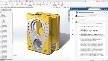
AI meets collaboration. With AURA integrated directly into 3DSwym, users can instantly summarize posts, wikis, and Q&As or pull in insights from entire discussions to drive smarter conversations.
These enhancements deliver faster insights and more informed collaboration with less manual searching.
2. Collaboration Directly Inside SOLIDWORKS
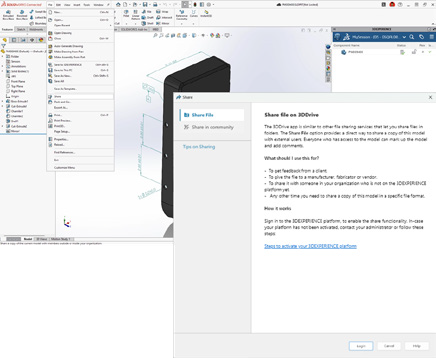
Work together without ever leaving your design space. Collaborate through the SOLIDWORKS User Forum, share files via 3DDrive and 3DSwym, and eliminate the need for conversions or third-party tools.
These enhancements deliver smoother teamwork and more efficient communication with less switching between tools.
3. Drawing Stamping with Maturity Status
Simplify change management with automatic maturity status stamps. User names and emails are embedded in drawings for full traceability and accountability throughout the design lifecycle.
These enhancements deliver clearer documentation and more reliable approvals with less manual tracking.
4. Cut List Management on the 3DEXPERIENCE Platform
Cut list data can now be fully managed on the platform, enabling tighter integration between EBOM and MBOM.
These enhancements deliver better alignment between design and manufacturing with less data re-entry.
5. Recent Files by Active Tenant
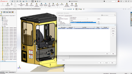
For teams managing multiple tenants, SOLIDWORKS 2026 now filters your recent files to show only those from the active tenant.
These enhancements deliver cleaner organization and faster access with less confusion.
6. Excel File Management for Design Tables
Design table management is now more reliable thanks to Excel file support on the 3DEXPERIENCE platform. This ensures version consistency, better automation, and stronger data integrity.
These enhancements deliver greater consistency and more reliable design automation with less manual version control.
7. Support for Deformable Components
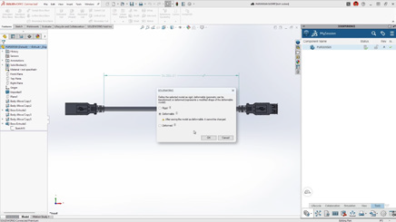
Easily switch between rigid and deformed part states in assemblies for improved accuracy and flexibility.
These enhancements deliver faster detailing and more accurate assemblies with less manual effort.
8. Automatic Bookmark Content Updates
Bookmarks now update automatically each session, ensuring you always access the latest design data, no manual refresh needed.
These enhancements deliver up-to-date project information with less time spent managing data.
9. Enhanced Bookmark Editor
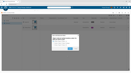
A redesigned Bookmark Editor delivers faster navigation and smarter selection when multiple bookmarks exist.
These enhancements deliver clearer navigation and more accurate project organization with less manual searching.
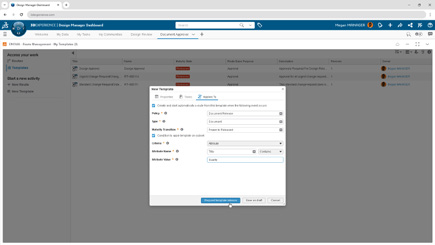
Large organizations gain new governance power with automated approval workflows tied to document maturity. Predefined routes trigger automatically for consistent, traceable, and compliant approvals.
These enhancements deliver stronger governance and more reliable approvals with less administrative overhead.
A New Standard for Collaboration and Data Management
SOLIDWORKS 2026 builds on its legacy of innovation with a sharper focus on collaboration, automation, and traceability. These ten enhancements don’t just make design faster, they make teamwork more intelligent, connected, and efficient across every stage of product development.
Join our official SOLIDWORKS 2026 launch to see these new features in action and get your questions answered by our experts!
SOLIDWORKS 2026 continues the trend of making design faster, smarter, and more connected. With AI-powered tools, streamlined workflows, and deeper collaboration features, this release is all about helping engineers and designers work more efficiently while maintaining accuracy and flexibility.
Here are the Top 10 Enhancements you need to know:
1. AI-Powered Design and Detailing
Artificial intelligence is making a real impact in everyday CAD workflows:
Automated drawing creation with AI-driven views, hole callouts, dimensioning, detailing, and even sheet format selection.
AI assembly recognition can now automatically detect and insert fastener-like components (nuts, bolts, washers), reducing repetitive tasks and improving assembly accuracy.
These enhancements deliver faster detailing and more accurate assemblies with less manual effort.
2. Large Assembly Performance
Large assemblies are now easier to manage:
Open massive designs faster by filtering only what you need from the 3DEXPERIENCE platform.
Skip rebuilds when only cosmetic changes are made.
Disable auto-resolve for lightweight components to improve responsiveness.
Together, these updates create smarter workflows that keep even the largest projects running smoothly.
3. Improved User Experience
Offline mode ensures uninterrupted productivity during internet disruptions.
A redesigned UI highlights common commands, helping new users get up to speed quickly.
Command Search now includes an expanded, customizable set of keywords.
The result is a smoother learning curve and less frustration for both new and experienced users.
4. Streamlined Part Design
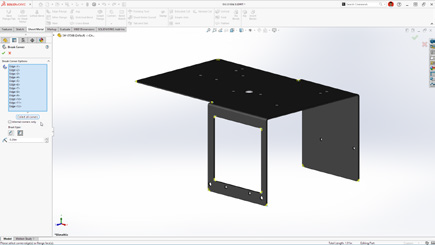
Define a custom start point for sheet metal base flanges.
Break internal corners on folded geometry.
Quickly create square sketch geometry in one click.
Track maturity changes and drawing history with Evaluated Attributes.
These improvements enable faster sketching and greater flexibility in sheet metal design.
5. Collaboration & Data Management
Share designs directly via 3DDrive and 3DSwym.
Update files to the latest version on the 3DEXPERIENCE platform with a single action.
Access the SOLIDWORKS User Forum from within the software.
With these tools, staying in sync with your team and your data has never been easier.
6. Drawing Detailing & MBD
Insert Family Tables into drawings for configuration details.
Use magnetic lines to align not just balloons, but notes, weld symbols, and other annotations.
Propagate DimXpert dimensions to library features and selectively manage annotation visibility.
This gives designers more control and clarity when documenting their designs.
7. Routing, Electrical, and Piping
Combine routing BOMs across subassemblies for a clearer overall materials list.
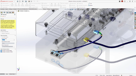
Place clips, mounts, and hangers directly in assemblies for flexible routing.
Visual indicators help guide splice placement in harnesses and wire bundles.
This gives designers more control and clarity when documenting their designs.
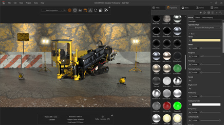
8. Rendering Enhancements
Control tessellation for a balance of geometry quality and performance.
Improved denoising in CPU mode reduces render noise in fewer passes.
Expanded format support with PBR materials in USDZ and glTF.
This gives designers more control and clarity when documenting their designs.
9. ECAD/MCAD Collaboration
Track parent/child PCB data like keep-in, keep-out, plated and non-plated holes.
Use CircuitWorks™ with IDX 3.0 support to review and even undo MCAD changes before final ECAD updates.
This gives designers more control and clarity when documenting their designs.
10. Import/Export
Simplify complex multibody parts faster by using advanced selection tools to efficiently isolate and manage bodies based on similarity or size.
Share assemblies saved on the 3DEXPERIENCE platform using the Export as Package option in the Share dialog box.
Streamline exports by choosing whether to include drawings in your package, for greater control.
This gives designers more control and clarity when documenting their designs.
Final Thoughts
With AI-powered automation, large assembly improvements, smarter part tools, and seamless collaboration, SOLIDWORKS 2026 makes it easier than ever to move from concept to finished product. Whether you’re creating complex assemblies, detailing drawings, or collaborating across disciplines, this release delivers tools to help you work smarter, faster, and with greater confidence.
Take your designs to the next level with SOLIDWORKS 2026. Contact us today to unlock smarter, faster, AI-powered engineering.
When we talk about AI, certain fears arise: could AI replace the engineer or the designer? The answer is no. Dassault Systèmes’ philosophy is very clear: AI does not replace, it enhances. After 11 years at S0lidxperts and more than 15 years of using SOLIDWORKS, I am well aware of this fact.
SOLIDWORKS, one of the most trusted CAD platforms globally, has already begun integrating AI-driven tools that assist engineers in reducing repetitive tasks, improving design quality, and accelerating time-to-market. Through the 3DEXPERIENCE platform, Dassault Systèmes is also paving the way for AI-powered collaboration and predictive design in the cloud.
In this article, we’ll explore how AI is shaping the present and future of SOLIDWORKS, highlight the business benefits, and share how Solidxperts, over 40 years in the industry and more than 25 years as a SOLIDWORKS partner, supports companies in embracing this transformation.
1. AI in SOLIDWORKS: An Engineer’s New Ally
Dassault Systèmes’ vision has always been clear: AI does not replace engineers. It enhances their capabilities. For decades, SOLIDWORKS has incorporated automation features designed to simplify CAD workflows:
Smart Mates for automatic assembly constraints.
Command Prediction suggesting the most likely next tool.
These were early steps toward intelligent CAD. Today, SOLIDWORKS goes further with AI-driven assistants like Design Assistant, and cloud-based tools powered by machine learning through the 3DEXPERIENCE platform.
The philosophy is simple: let AI handle the repetitive and time-consuming tasks, so engineers can focus on innovation, creativity, and solving real engineering challenges.
2. Current AI-Driven Features in SOLIDWORKS
a) Design Assistant
Mate Helper and Selection Helper: automatically detects similar components and applies constraints, drastically reducing clicks in large assemblies.
Example: When assembling dozens of fasteners, Design Assistant identifies similar geometry and instantly applies consistent mates.
b) Automatic Drawings (SOLIDWORKS 2025)
Automatically generates 2D drawings from 3D models.
Ensures compliance with drawing standards.
Saves significant time in documentation, especially for design offices managing large projects.
c) Fastener Recognition (FD03)
Automatically detects standard fasteners in assemblies.
Applies appropriate mates without manual intervention.
Direct impact: reduced errors, fewer repetitive operations.
d) AURA: The Conversational AI Assistant
Integrated into the 3DEXPERIENCE platform.
Provides contextual guidance to users, learns from workflows, and offers predictive insights.
Example: guiding new users through advanced features or assisting with design standards.
3. The Future of AI in SOLIDWORKS: A Roadmap
Dassault Systèmes continues to push boundaries, and the AI roadmap promises groundbreaking advancements:
Mesh to Parametric Conversion (Reverse Engineering): AI will streamline converting mesh files into fully parametric models, accelerating reverse engineering processes.
AI-Optimized Assemblies: Automatic detection of redundant constraints, performance optimization, and manufacturability checks.
AI-Generated Photorealistic Renders: Leveraging generative AI to instantly create marketing-ready visuals without lengthy manual rendering.
xDesign and Cloud-Ready AI: The 3DEXPERIENCE xDesign app represents the next generation of CAD: cloud-based, AI-enhanced, and fully collaborative.
Vision: Predictive, Collaborative CAD: An environment where the system anticipates design intent, suggests optimizations, and improves with each project.
4. Strategic Benefits for Companies
Adopting AI in SOLIDWORKS is not just about convenience—it drives measurable business impact:
Productivity: Significant time savings through automation of repetitive tasks.
Quality: Consistent designs, fewer human errors, and adherence to standards.
Innovation: Engineers gain more time to focus on R&D and creative problem-solving.
Competitiveness: Faster time-to-market and optimized workflows lead to a competitive edge.
Use Cases:
Design offices managing large assemblies save hours on constraints.
Manufacturers preparing technical documentation see accelerated drawing creation.
Teams leveraging AURA gain training efficiency and reduced onboarding time.
5. Data Security and Confidentiality
AI adoption often raises concerns about data protection. Dassault Systèmes has addressed this head-on:
Your proprietary data is not shared or trained externally without explicit consent.
Companies can configure private AI models trained on their own part libraries and workflows.
This ensures both innovation and confidentiality which is critical for SMEs and global enterprises alike.
6. Solidxperts: 40 Years of Experience, Always Evolving with AI
The evolution of Solidxperts over the past four decades reflects the same philosophy as SOLIDWORKS: constant growth, adaptation, and customer focus.
1998: Solidxperts opened its main office in Montreal, introducing clients to SOLIDWORKS back then, delivered on physical CDs.
Today: Solidxperts delivers the full Dassault Systèmes portfolio, from SOLIDWORKS to the cloud-based 3DEXPERIENCE platform, supporting every step of the design-to-manufacturing journey.
Values: transparency, dedication to customer success, and a personalized approach embedded in every interaction.
Expansion: with offices in Quebec City (QC) and Nashua (NH), Solidxperts serves engineers and businesses across Eastern Canada and New England.
This long-term experience positions Solidxperts as the partner of choice for companies looking to adopt AI-powered CAD and manufacturing solutions.
The Future is Now with SOLIDWORKS AI
Artificial Intelligence is no longer an abstract concept. Iit is already part of the tools engineers use daily in SOLIDWORKS. From automated mates to predictive design and cloud collaboration, AI is redefining the engineering experience.
For businesses, embracing AI in SOLIDWORKS means:
Faster workflows
Fewer errors
More time for innovation
Stronger market competitiveness
At Solidxperts, we’ve supported thousands of engineers and companies for over 25 years with SOLIDWORKS, and we are ready to help you take the next step: integrating AI into your design and manufacturing workflows.
Contact our experts today to schedule a personalized demo and discover how AI in SOLIDWORKS can transform your business.
Since the dawn of engineering, predicting how a part behaves under load has always been a challenge for designers. Today, we have advanced simulation methods built on decades of research and development. Yet, simulating a 3D-printed part remains complex.
Most modeling software still doesn’t account for the anisotropic properties of 3D printing, especially when it comes to continuous fiber reinforcements like those offered by Markforged.
Additive manufacturing, with its fast iteration cycles, does allow multiple versions of a part to be printed and tested in order to converge on an acceptable solution. But this approach has its limits: some problems are long and costly to solve, both in time and in material.
This is where Eiger comes in. Markforged’s software integrates a simulation and optimization module designed to bring the printed part’s real-world performance closer to the design goals, right from the first print.
So, what is this software really worth? Just marketing fluff, or a genuine game changer for the industry? Let’s dig deeper.
1. Access to Simulation
Simulation is only available with the Advanced Digital Forge plan. Once activated, you simply import a part into Eiger, define the printing parameters, and head to the SIM tab.
Want to learn more about the Advanced Digital Forge plan, get a personalized demo, or even test your own part optimizations? Contact us, we’ll be happy to help.
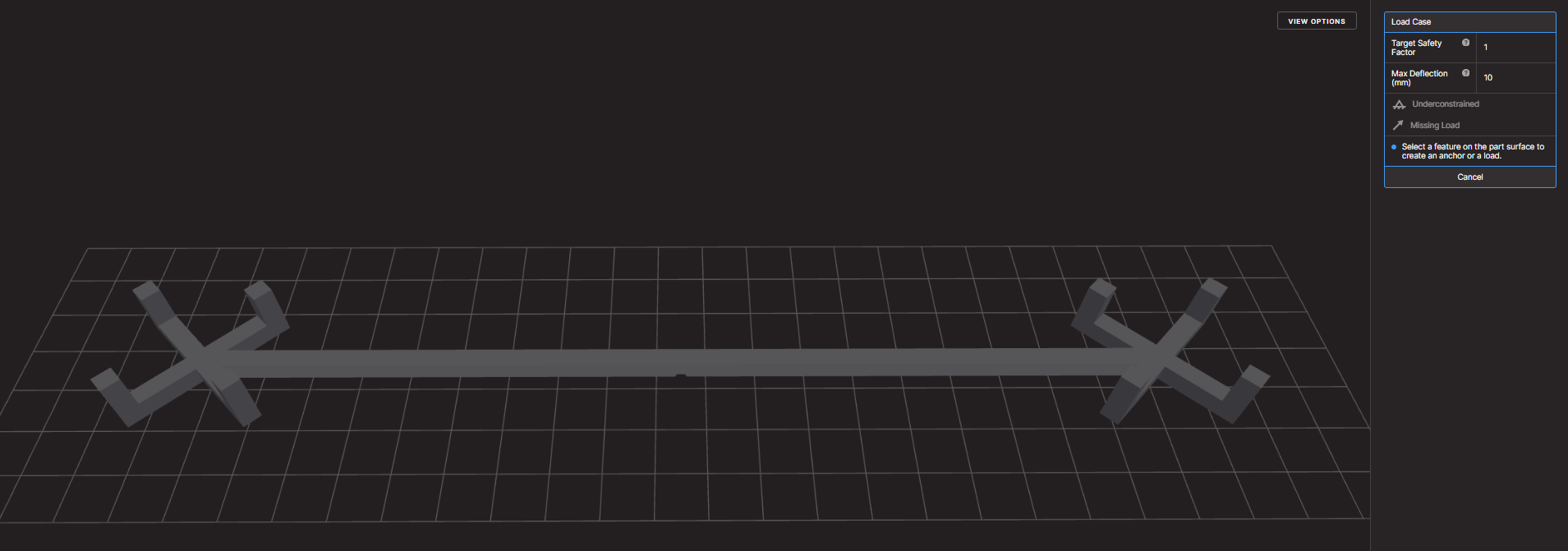
You’ll then see a 3D view of the part along with a panel for setting up the simulation conditions:
applied loads,
fixed surfaces or regions,
desired safety factor,
maximum allowable deflection.
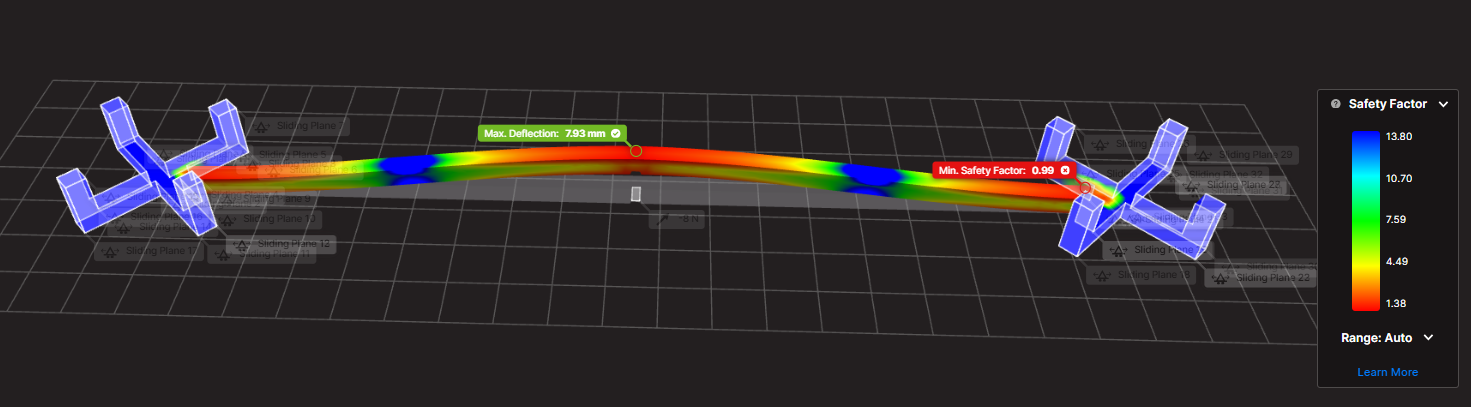
For this article, we used the example of a beam subjected to a bending force.
2. Defining and Running a Load Case
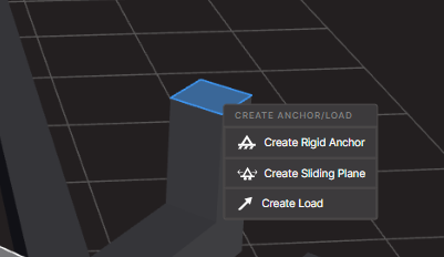
Each scenario is defined by selecting the relevant surfaces (for example, sliding planes or fixed supports) and applying a given force.
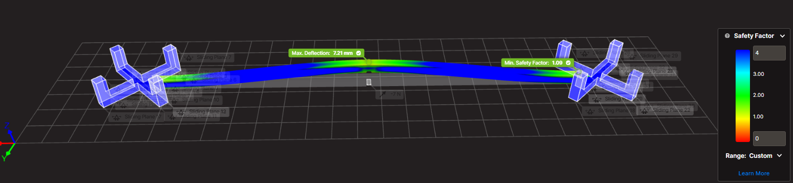
In our test, a force of 7.7 N was applied.
The simulation runs in the cloud, which eliminates the need to dedicate local resources or a separate server. While the calculation is running, you can continue working and return once the results are ready.
3. Simulation Results
The module then generates a color-coded 3D rendering highlighting:
the safety factor (stress vs. strength),
the maximum deflection.
Example:
With a 7.7 N load, the safety factor was 0.99 → failure expected.
The maximum deflection measured was 7.93 mm.
With a 7 N load, the safety factor rose above 1, meaning the beam could withstand the force but would fail around 7.7 N.
4. Limits and Interpretation
Like any simulation software, Eiger is based on an idealized model of the part, with theoretical load and constraint conditions. This means that results may vary depending on how the case is defined.
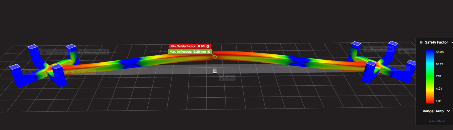
For example, for the same beam subjected to the same load, choosing between sliding planes or fixed supports can lead to two equally realistic simulations. The overall stress zones remain similar, but the location of the maximum stress changes.
This underlines a key rule: you can’t just take the raw results at face value, you need to analyze and interpret them carefully. The tool’s true value lies not only in calculation accuracy but also in the engineer’s ability to understand what the results mean for the design.
Fortunately, thanks to the color visualization and customizable table, critical areas are easy to spot. In our test, three clear stress concentration zones were identified, allowing the designer to anticipate issues and reinforce the part at the design stage.
From Theory to Practice: Eiger as an Innovation Accelerator
Eiger is more than just a slicer for Markforged printers, it’s a design tool. It enables simulation of multiple designs, performance forecasting, and significant time savings before the first physical test.
In our next article, we’ll look at strategies for optimizing a part after simulation and compare the virtual results with real-world testing to validate failure thresholds.
Want to go further? Reach out to our team to explore the Advanced Digital Forge plan, schedule a demo, or benefit from a personalized analysis of your parts.
SOLIDWORKS is the gold standard for 3D CAD. Yet, when used in many industries, including mechanical engineering and product design. However, as a timber design software, it has certain limitations in terms of 3D timber modelling and timber production optimisation. As a result, when it comes to wood design and manufacturing, these limitations can make the process less efficient and more error prone. Therefore, to address this challenge, this is where SWOOD, a supplement specially designed for cabinetry, carpentry, interior design, and even the current trend VanLife! comes into play. This solution brings features specific to the wood trade that perfectly complement SOLIDWORKS, facilitating the transition from design to production.
In this article, we’ll explore in detail why SWOOD is a strategic choice for optimizing your wood designs in SOLIDWORKS, highlighting its benefits, features, and impact on the productivity and profitability of companies in the industry.
SOLIDWORKS: A Powerful but Generalist Foundation
SOLIDWORKS is widely recognized for its flexibility in mechanical and industrial design. Key strengths include:
An intuitive, parametric 3D environment facilitating the design of complex parts and assemblies
Moreover, extensive integration with analysis and simulation tools (material strength, airflow, kinematics, etc.)
In addition, advanced management of assemblies and drawings for production
Finally, a rich ecosystem of plugins and third-party solutions to extend its capabilities according to the user’s needs
However, SOLIDWORKS remains a general-purpose software. In the context of wood design, several limitations are felt:
Firstly, lack of native management of panels and wood-based materials (MDF, laminate, plywood, etc.)
Secondly, complexity of creating specific connections (grooves, mortise and tenons, lamellos, etc.)
Another limitation is the lack of bookcases suitable for hardware components commonly used in layout and millwork
Finally, the need to develop macros or scripts to automate certain recurring tasks. Consequently, it is in this context that SWOOD brings considerable added value.
SWOOD: Ideal complement for wood design
SWOOD is a set of modules developed specifically for the wood sector, offering a complete solution tailored to the needs of carpenters and furniture manufacturers. Unlike other generalist software, SWOOD stands out for its dedicated approach, integrating a wood CAD plugin that automates the design and assembly of panels, hardware and specific machining. Through woodworking automation, SWOOD helps significantly reduce errors, optimize material usage, and speed up the transition from design to manufacturing, making the process smoother, more cost-effective, and designed to integrate seamlessly with SOLIDWORKS. In other words, it offers dedicated tools that simplify the design and production of wooden furniture, fixtures and structures.
The main modules of SWOOD
SWOOD Design
Advanced panel management, with automated creation of cutouts and assemblies
Smart libraries of hardware and standard elements (hinges, slides, fasteners, etc.)
Generation of detailed bills of materials to optimize purchasing and production
Automation of wood assemblies and constraints
SWOOD CAM
Machining module for generating CNC programs adapted to machines in the woodworking sector
Automatic recognition of drilling and machining
Machining simulation to detect possible errors before production
Support for 3, 4 and 5 axis machines
SWOOD Nesting
Optimization of the placement of parts on the panels to limit falls and reduce costs
Advanced management of formats and machining priorities
Management of facades and grouping of items by blank slabs
SWOOD Center
Product configurator for the wood industry
SWOOD Center is an advanced solution for configuring tailor-made products in the world of wood and fittings. Integrated with SOLIDWORKS, this configurator optimizes process design, production, and automation.
Why choose SWOOD Center?
Advanced customization
Parametric configuration of furniture and layouts
Managing product variants and options
Dynamic visualization of changes
Workflow automation
Automatic generation of production files (drawings, bills of materials, CNC programs)
Integration with SWOOD Design and SWOOD CAM
Material optimization and error reduction
Time saving and efficiency
Reduced design time
Simplifying processes for technical and business teams
Improved responsiveness to customer requests
An ideal solution for manufacturers and fitters
Thanks to SWOOD Center, wood professionals can standardize their designs while offering tailor-made solutions to their customers. This configurator is particularly suitable for carpenters, fitters, kitchen designers and furniture manufacturers who want to modernize their design and manufacturing process.
By integrating SWOOD Center into your workflow, you can accelerate your product time-to-market while ensuring a reliable and accurate design.
The Benefits of an Integrated SOLIDWORKS + SWOOD Solution
By combining both solutions, using SOLIDWORKS and SWOOD together provides many benefits, including:
Time saving: Automation of repetitive tasks such as inserting fasteners, managing panels and exporting files for production
Reduction of errors: Consideration of the specificities of the wood from the design stage, thus limiting corrections during the manufacturing phase
Full shop floor compatibility: Ability to generate CNC files that can be used directly by machine tools
Cost optimization: Less scrap, better management of raw materials and reduction of production times
Improved collaboration: Easier integration with other departments in the company, including production and purchasing teams
Altogether, these advantages allow manufacturers to gain in competitiveness while guaranteeing optimal quality to their customers.
With SWOOD, companies can streamline their design processes, reduce human error, and maximize shop floor efficiency. As a result, manufacturers can confidently move from design to production.
SWOOD Testimonial: Reviews and Case Studies
For instance, many carpentry and layout companies have successfully adopted SWOOD. Here is a concrete example:
A concrete example is Groupe Beaubois which faced the challenge of improving the efficiency of its project and streamlining its operations. To achieve this, he needed to embrace technological advancements and integrate automation and robotization into his factory. However, he quickly realized that his design software played a vital role in facilitating the flow of information on his equipment. That’s when he discovered the SWOOD solution, which was specially designed for the wood industry.
Text: Groupe Beaubois boosts efficiency and growth thanks to SWOOD
Return on investment and development prospects
From a business perspective, investing in SWOOD represents an initial cost that is quickly amortized thanks to productivity gains. Here are a few things to consider:
Learning time: Quick training is often enough to master the basics of the software
Material savings: Better cutting management and reduced errors
Valuation of internal skills: Designers gain autonomy and efficiency
In the future, the integration of SWOOD with technologies like artificial intelligence and 3D printing could further improve the performance of the industry.
From Design to Production Without Limits
In conclusion, if your processes are disconnected and your work seems to be in silos! Whether you’re switching from one solution to another to get your production up and running, the SOLIDWORKS + SWOOD combination is a powerful, comprehensive solution that’s perfect for you. It helps optimize design, improve accuracy, and increase efficiency, while reducing costs and errors. By integrating SWOOD into your workflow, you ensure better control of your production and increased competitiveness in the market.
Therefore, if you’d like to learn more about SWOOD and its integration with SOLIDWORKS, request a demo of SWOOD for wood design today and learn how to optimize your woodworking and layout projects! Contact us or request a demo today!
In the field of industrial design and steel construction, efficiency, precision, and seamless integration of design tools are key success factors. Industry professionals face technical, economic, and time-related challenges that require high-performance software solutions. SolidSteel for SOLIDWORKS stands out as a parametric 3D modeling solution dedicated to steel construction within SOLIDWORKS. This innovative tool allows engineers and designers to save valuable time while meeting industry standards and optimizing the design process from initial sketches to fabrication.
Target Market for SolidSteel for SOLIDWORKS
SolidSteel for SOLIDWORKS is primarily aimed at engineering firms, civil engineers, steel fabricators, manufacturers of steel structures, and any company specializing in steel construction. It is especially useful for businesses that work on complex structural projects such as industrial walkways, frames, or structures for specialized machinery. Its deep integration with SOLIDWORKS makes it a natural choice for users already familiar with this widely adopted CAD platform in the industrial sector.
This product is also ideal for manufacturing companies equipped with CNC production workshops, as data export in the DSTV format facilitates the transition from digital design to physical fabrication. The target market is therefore broad, ranging from SMEs to large international companies in construction, energy, transportation, or heavy manufacturing industries.
Added Value and Problems Solved with SolidSteel
While designing steel structures in SOLIDWORKS is possible, it can quickly become tedious and time-consuming using only standard tools. SolidSteel for SOLIDWORKS fills this gap by providing features specifically tailored to steel construction:
Automatic generation of standard profiles according to DIN, EN, ASTM, and other norms
Automated connections (welds, bolts, base plates, etc.)
Calculation and management of cuts, notches, and complex angles
Fast creation of fabrication drawings and part lists
Integration of manufacturing and assembly constraints at the design stage
Libraries of standard components to save time on repetitive projects
Generation of complex assemblies with interference management
Thanks to these features, SolidSteel for SOLIDWORKS eliminates human errors, shortens design timelines, and improves the overall quality of metal structure projects. It also enables companies to be more competitive by allowing them to respond quickly to tenders with accurate designs, automated quotes, and realistic planning.
Seamless Integration into SOLIDWORKS
One of the major strengths of SolidSteel for SOLIDWORKS is its native integration within the SOLIDWORKS interface. Unlike external software solutions, SolidSteel functions as a natural extension of the engineer’s daily work environment. Users benefit from a consistent ergonomic experience without needing to learn new software or change their existing workflow.
With bidirectional integration with other SOLIDWORKS modules, users can combine SolidSteel for SOLIDWORKS with structural simulation (SOLIDWORKS Simulation), stress analysis, or technical documentation generation (SOLIDWORKS Composer), thus enhancing efficiency and precision throughout the entire process.
This integration also allows users to leverage all the powerful features of SOLIDWORKS (assemblies, configurations, drawings, simulation, etc.) while adding specialized tools for steel design. This synergy ensures a smooth workflow from design to production.
Competitive Advantages of SolidSteel
SolidSteel for SOLIDWORKS offers several advantages that set it apart from the competition:
Intuitive interface tailored to SOLIDWORKS users
Advanced customization of connection templates
Fast modeling with intelligent placement tools
Compatibility with international standards
Automated documentation and traceability features
Scalable solution based on client needs
These benefits help companies standardize their design processes while maintaining the flexibility needed to meet specific project requirements. SolidSteel for SOLIDWORKS is therefore a strategic tool for digital transformation in the steel industry.
Training Offered by Solidxperts on SolidSteel for SOLIDWORKS
To help professionals get the most out of SolidSteel for SOLIDWORKS, Solidxperts—an expert SOLIDWORKS solutions partner—offers a comprehensive range of training programs tailored to various needs. These training sessions cover the different SolidSteel modules:
SolidSteel Parametric for accurate and parametric 3D design of complex steel structures
SolidSteel Frame for rapid creation of steel frames and structures
SolidSteel Manufacturing for fabrication preparation, including production drawings and assembly management
Training includes:
Hands-on sessions with each module in the SOLIDWORKS environment
Best practices for modeling steel structures
Creation of smart and customizable connections
Automatic generation of drawings and BOMs
Production process optimization
Export to DSTV format for automated machining of profiles in the workshop (crucial for interoperability with CNC production lines in the steel construction industry)
Automation of technical documentation and bill of materials
Solidxperts offers flexible training formats: online, in-person, onsite at the client’s location, or at their own facilities. In addition, personalized post-training support is provided to ensure proper integration of SolidSteel for SOLIDWORKS into the team’s daily operations. Advanced workshops can also be arranged on topics such as connection optimization, BIM export, or project revision management.
Use Cases and Customer Feedback on SolidSteel for SOLIDWORKS
Several companies that have adopted SolidSteel for SOLIDWORKS report significant gains in productivity and quality. For example, a steel construction firm reduced its complex structure design time by 40% thanks to automatic connection and drawing generation. Another company integrated DSTV files directly into its CNC machines, eliminating intermediate reprogramming steps.
These success stories highlight the tangible impact SolidSteel for SOLIDWORKS has on project profitability. It’s not just a design assistant. It’s a true catalyst for efficiency and innovation.
The Future of Steel Design with SolidSteel for SOLIDWORKS
SolidSteel for SOLIDWORKS is much more than just a plugin: it’s a comprehensive solution that transforms how steel structures are designed, documented, and manufactured. With its seamless integration, powerful tools, and specialized training offered by Solidxperts, professionals gain a strategic edge in both efficiency and quality.
By combining technical performance, industry compatibility, and human support, SolidSteel for SOLIDWORKS empowers companies of all sizes to advance their digital transformation. For any business looking to streamline steel design while relying on the reliability of SOLIDWORKS, SolidSteel is the obvious choice.
Whether you’re an engineer, drafter, project manager, or workshop supervisor, SolidSteel for SOLIDWORKS helps you tackle the challenges of modern steel construction with precision, speed, and confidence.
Ready to take your steel design process to the next level? Contact Solidxperts today to learn how SolidSteel for SOLIDWORKS can transform your projects.
Any questions? Need help? Ask one of our experts.
Whether you’re ready to get started or just have a few more questions, you can contact us toll-free:
We are pleased to announce the upcoming arrival of the updated version of SWOOD 2025 solutions, eagerly awaited by professionals working with wood, both in cabinets, architectural cabinetry, and any type of layout. In fact, the new SOLIDWORKS, SWOOD innovations are attracting lots of interest.
Moreover, the updated version, which will be available soon, includes several notable improvements to the SWOOD software suite. Here is a summary of the main advances, structured around the three pillars of the new SWOOD 2025 products.
This is an overview of what’s new. Contact us for more details, as each new feature can have several aspects.
The 3 Pillars of SWOOD 2025
Design
Manufacturing
Automation
Pillar 1: Design
Panel Cutting Improvements
Panel cutting was introduced with SWOOD 2024 and has undergone some improvements this year. For example, improvements around the user experience by adding for example a help button, it is now possible to pin the function and therefore to chain the different cuts. Finally, the highlighting of interference has been added.
Edge Banding Length Feature
From the Edge Library or, from the Edge function, in the Design Tree, you will have the choice to set an over-field length. This overlength is going to be mostly used in the report or the total length in the report. As a result, you will have a reliable estimate.
Easy Customization of SWOODBox
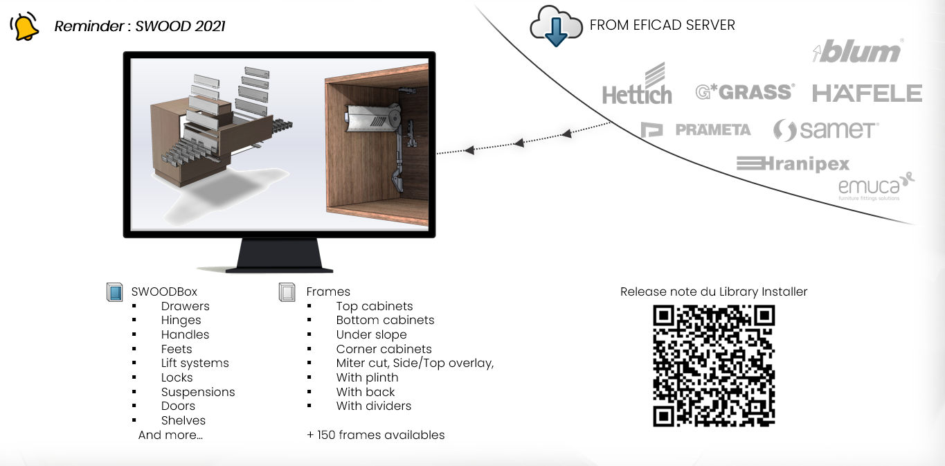
Thanks to the library installer you have access to links too! For example, hinges, inserting default settings allows you to quickly create SWOODBox! Therefore, you can save them to your SWOODBox library and quickly reuse them.
Improved User Experience
Right-clicking allows you to collapse folder contents, reducing the number of clicks and making navigation faster and more intuitive. This also eliminates the need for endless scrolling when searching for the right folder.
Additionally, to further streamline navigation and enhance your overall experience, you can also make use of filters.
Performance Improvements
Significant enhancements have been made across multiple areas. PDM now handles copy operations more efficiently, while deletion states in SWOODBox have been optimized for smoother workflows. Texture and appearance management has also been improved, ensuring greater consistency. Finally, reporting has been streamlined for faster, more reliable results.
Order Manager Improvements
Similarly, the order managers, so SWOOD design and SWOOD Cam. What was done was to bring the SWOOD design and SWOOD Cam tools directly into these managers. This makes them more manageable and can even be reset to default if needed.
Library Installer Updates
The next Library installer that will arrive so there are about new features once a month, an update once every 2 weeks with new hardware and new elements. Furthermore, speaking of new elements, well, let’s move on to the SWOOD 2025 improvements.
Liaisons were something that was missing. And now? Well, we will have the possibility to download links from the free installer.
In addition, another new feature is that the elements that you are going to download are going to be blocked, but if you want to modify them, you will just need to duplicate them, copy them and then you can modify them according to your needs.
Panel Manager Enhancements
In particular, the panel manager is a tool developed a little over five years ago, with a first version released in 2020. Its main purpose is to add SWOOD data to existing CAD files, whether they are models designed only with SOLIDWORKS (especially before the introduction of SWOOD), multibody parts exported to assemblies or files imported in STEP format. The workflows and features of this tool have been fine-tuned to allow the manufacture of models that were not originally created with SWOOD.
New Conditional Filter Tool in SWOOD 2025!
These conditional filters will be found a little bit everywhere in the software. This will simply allow us to start from a list. Well, to set of, variables, parameters to filter a list.
Most importantly, the advantage is that these filters are intelligent so that they can be found in a library of materials or fields, for example.
Pillar 2: Manufacturing
CAM Copy Tool
Its accessibility has been simplified. We will find it directly from the Command manager so we will have easy access to it.
We will find 2 modes, the mode, the first mode is the copy mode or from the source strategy, we will be able to take this strategy, define either an assembly, a part or even a folder! to stick this strategy to the selections.
On the other hand, the second mode will allow us to duplicate from a nesting file to be able to duplicate them to a new post processor and so, for example, if we have several CNCs and Well, we will be able to duplicate all these elements, all these nesting sheets to a new machine.
Input and Output Machining Speed
The management of machining inputs and outputs will define how the tool will enter the material, we will be able to define a specific speed to avoid splinters and have a better rendering, for example. These are often parameters that are not necessarily available, so here we will have the possibility to do it directly with SWOOD cam and encode it on the machine.
3D Finishing Enhancements
In concrete terms, this is how it works: on this part, a new 3D finish is defined by selecting the relevant surfaces. Then, all the necessary options are chosen, for example by specifying that the tool should be positioned horizontally and then adjusting the appropriate angle. It is not possible in some cases to access certain areas. However, with the new undercut option, it becomes possible to treat these parts, along with a release option to ensure the safety of tool outlets. Simulation of the toolpath allows you to visualize these steps, and this feature opens up more possibilities for the manufacture of complex parts.
Nesting Improvements with the Auto Flip Detection
From a 3D file, SWOOD automatically detects parts that require flipping. Users can change this list if needed. When recalculating based on set parameters such as offset, flip direction, or reference corner, SWOOD finds which sheets have parts requiring reversal. This reduces unnecessary flips by grouping compatible parts on the same sheet.
SWOOD 2025 introduces the new Nesting from CSV
Let’s continue with the nesting feature that allows you to import data from a CSV file. Remember that the system report offers the possibility of exporting lists in CSV format. By simply specifying the file path and the desired quantity for one or more projects, we can export this CSV and then import it into the nesting module; it is possible to work with one or more CSV files. This flow automatically redefines the sources and their quantities, whether it’s an assembly or a part. A simple recalculation then allows the best nesting result to be obtained quickly. As a result, the transition from design to manufacturing is just a few clicks away, easing more correct production management without the need to manually search for the right files.
New Tilt Types in SWOOD 2025!
Five additional tilt angle configurations are now supported for more refined tool orientation control during 3D operations.
Pillar 3: Automation
General System Report Enhancements
Data Export: Data export has been improved with SWR format stabilization, a standalone viewer, and lighter data files that can now be created in just milliseconds. In addition, cutting patterns and board estimations have been refined for greater accuracy.
System Report: The new standard data export allows you to export all project data with multiple levels of detail (parts, panels, materials, hardware, programs, etc.). A project report history is also available for easy tracking.
Customize Data Views: You can now hide or show data levels, filter data views, display columns, export table views to CSV, and choose your preferred print layouts and much more.
Customize Views: Enhanced customization options make navigation easier: you can open documents directly from folder access, group data by variables, and add a calculation line (sum, count, average, min, max, etc.). In addition, you can now save your settings by creating profiles.
New SWOOD 2025 Data Sharing Method
This updated version offers a multitude of features, mainly focused on data sharing and collaboration within the company. It offers precise access management, whether online or offline.
About automation, significant improvements have been made to the system report. It is now possible to easily share all data and documents, without having to install more software, simply via a link accessible to the entire organization.
It’s Now Your Turn to Discover the Power of SWOOD 2025
SWOOD 2025 represents a major leap forward in woodworking design, manufacturing, and automation. The new features and enhancements covered here are only a glimpse of what the latest version has to offer. Indeed, whether you are optimizing your workflows, improving accuracy, or streamlining collaboration, SWOOD 2025 provides powerful tools to help you achieve more.
To fully explore how SWOOD 2025 can transform your projects, contact us today for personalized guidance and demonstrations.